
Controlled flow administration set

a flow control and set technology, applied in the direction of process and machine control, instruments, other medical devices, etc., can solve the problems of affecting the operation of the flow control device, forming bubbles, etc., and enhancing the elasticity of the conduit, preventing kinking

Active Publication Date: 2014-10-28
ACU RATE HLDG PTY LTD
View PDF19 Cites 6 Cited by
  • Summary
  • Abstract
  • Description
  • Claims
  • Application Information

AI Technical Summary

Benefits of technology

The patent describes a connector for medical devices that can be easily deformed for priming purposes. The connector has a cylindrical housing with two sockets and a flexible web between them. The housing is made of a flexible material that allows for easy priming. The connector can be reinforced with a reinforcing member to prevent kinking and make the conduit more elastic. The reinforcing member can be made of plastic, metal, or shape memory alloy. Overall, the patent describes a connector that is easy to use and can be adapted to a variety of medical needs.

Problems solved by technology

Thus there is no chamber in which air bubbles can form which could inhibit proper operation of the flow control device.

Method used


Image

  • Controlled flow administration set
  • Controlled flow administration set
  • Controlled flow administration set

Examples


Embodiment Construction

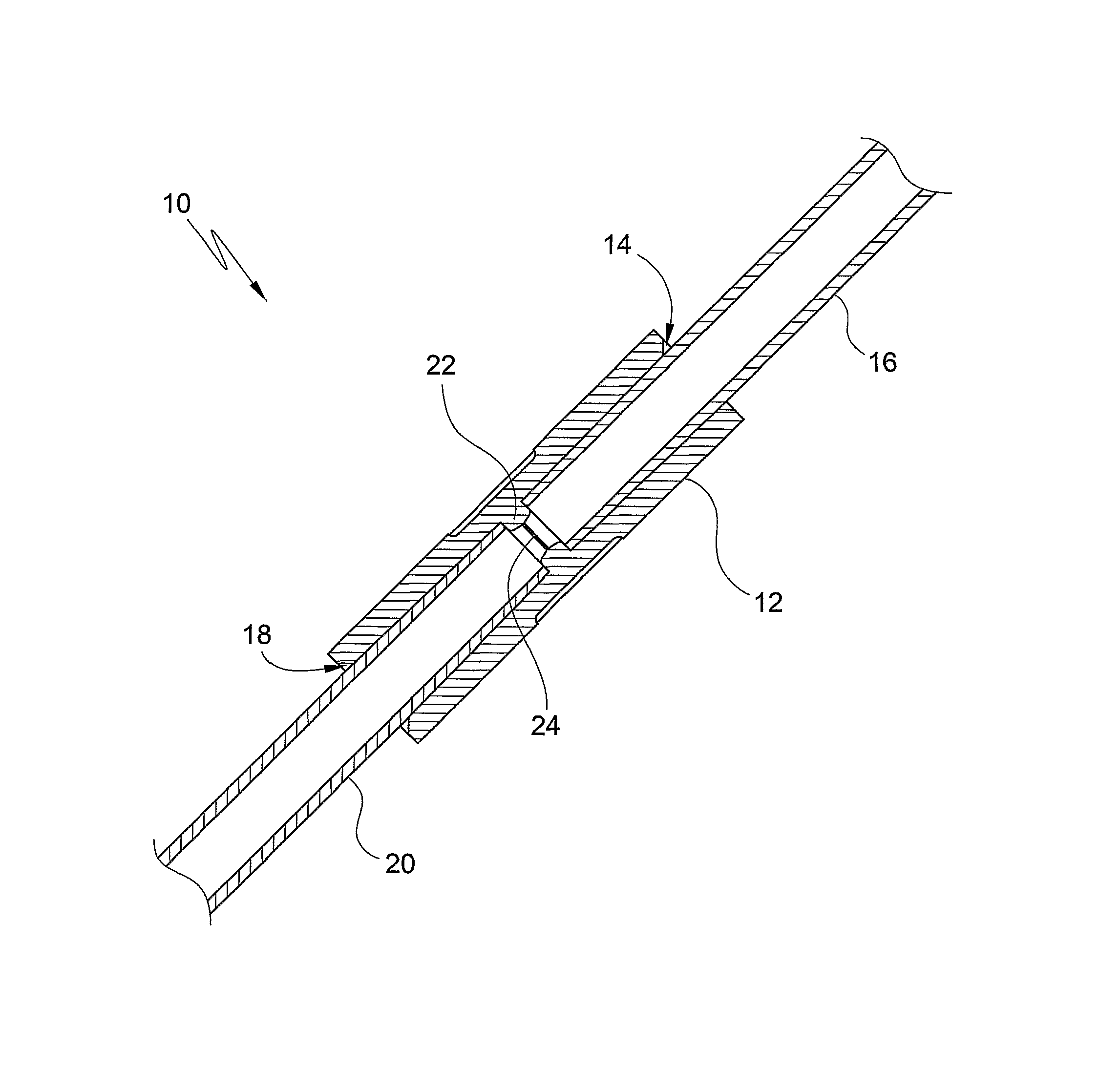
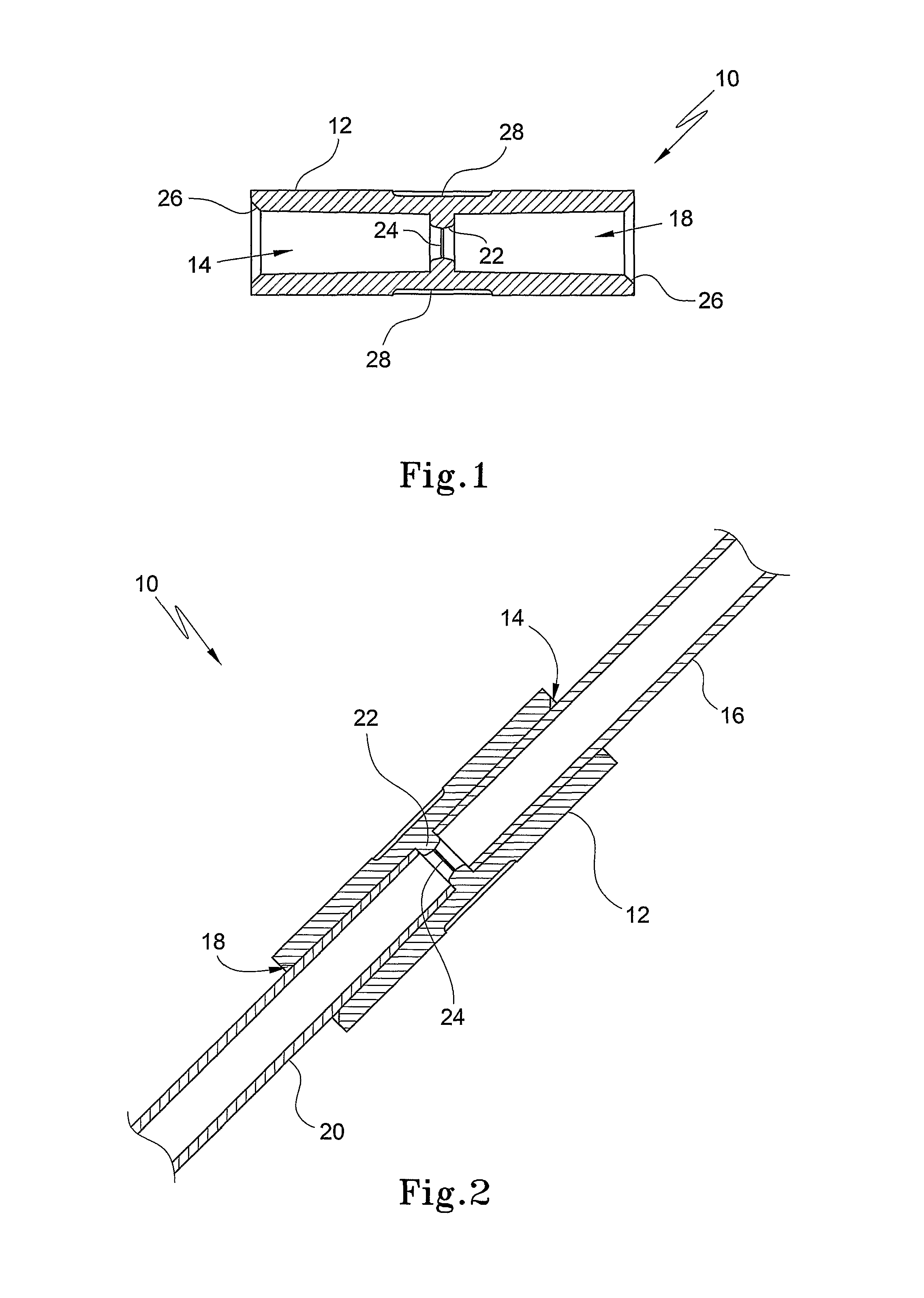
[0058]Referring initially to FIGS. 1 and 2 of the drawings, an embodiment of a flow control device is designated generally by the reference numeral 10. The flow control device 10 comprises a connector in the form of a housing 12. The housing 12 defines a first receiving formation 14 in which a first conduit 16 (FIG. 2) is received and a second receiving formation 18, spaced from the first receiving formation 14, in which a second conduit 20 is received. The receiving formations 14 and 18 are arranged on opposed sides of a cross member, or web, 22. The web 22 supports an orifice plate 24, the orifice plate 24 being a separate component and defining a frustoconical orifice 34 which will be described in greater detail below.

[0059]The housing 12 is of a resiliently flexible material. The housing 12 is of a polymeric material or, instead, is of an elastomeric material, more particularly, a silicone material.

[0060]It will be noted that each receiving formation 14, 18 is slightly tapered t...


PUM


Abstract

A flow control device (10) includes a connector (12) defining a first receiving formation (14) for receiving a first conduit, a second receiving formation (18) for receiving a second conduit and a cross member (22) separating the first receiving formation (14) and the second receiving formation (16). An orifice plate (24) is received in the cross member to control flow of fluid, in use, through the conduits received in the first and the second receiving formations (14, 18) of the connector (12), the orifice plate (24) defining at least one substantially frustoconical orifice (34).

Description

CROSS-REFERENCE TO RELATED APPLICATIONS[0001]This application is the national phase, under 35 U.S.C. §371, of International Application No.: PCT / AU2006 / 001465, filed Oct. 5, 2006, which designated the United States of America and which claimed priority to Australian Provisional Application No. AU 2005905494 filed Oct. 5, 2005. The present application claims the benefit of priority to and incorporates herein by reference, in their entirety, the disclosures of International Application No.: PCT / AU2006 / 001465 and Australia Application No. AU 2005905494.FIELD OF THE INVENTION[0002]This invention relates to a flow control device. More particularly, the invention relates to a flow control device particularly, but not necessarily exclusively, for use in an intravenous (IV) administration set, to an orifice plate for a flow control device and to a component for an IV administration set.BACKGROUND OF THE INVENTION[0003]At present, infusion of fluids into a patient is managed by medical perso...

Claims


Application Information

Patent Timeline
Patent Type & Authority Patents(United States)
IPC IPC(8): A61M5/14A61M5/168A61M5/175A61M39/10
CPCA61M39/10A61M5/16877A61M2205/6081A61M2005/1402A61M5/168A61M39/08
Inventor MILIJASEVIC, ZORAN
Owner ACU RATE HLDG PTY LTD
Learn More