
Endless track for propelling a vehicle, with edge-cutting resistance

a technology of endless tracks and vehicles, applied in endless track vehicles, vehicles, transportation and packaging, etc., can solve the problems of premature deterioration of the track, affecting the smoothness of the track, so as to facilitate the elastic deformation of the lateral edge par

Active Publication Date: 2016-12-06
CAMOPLASY INC
View PDF242 Cites 7 Cited by
  • Summary
  • Abstract
  • Description
  • Claims
  • Application Information

AI Technical Summary

Benefits of technology

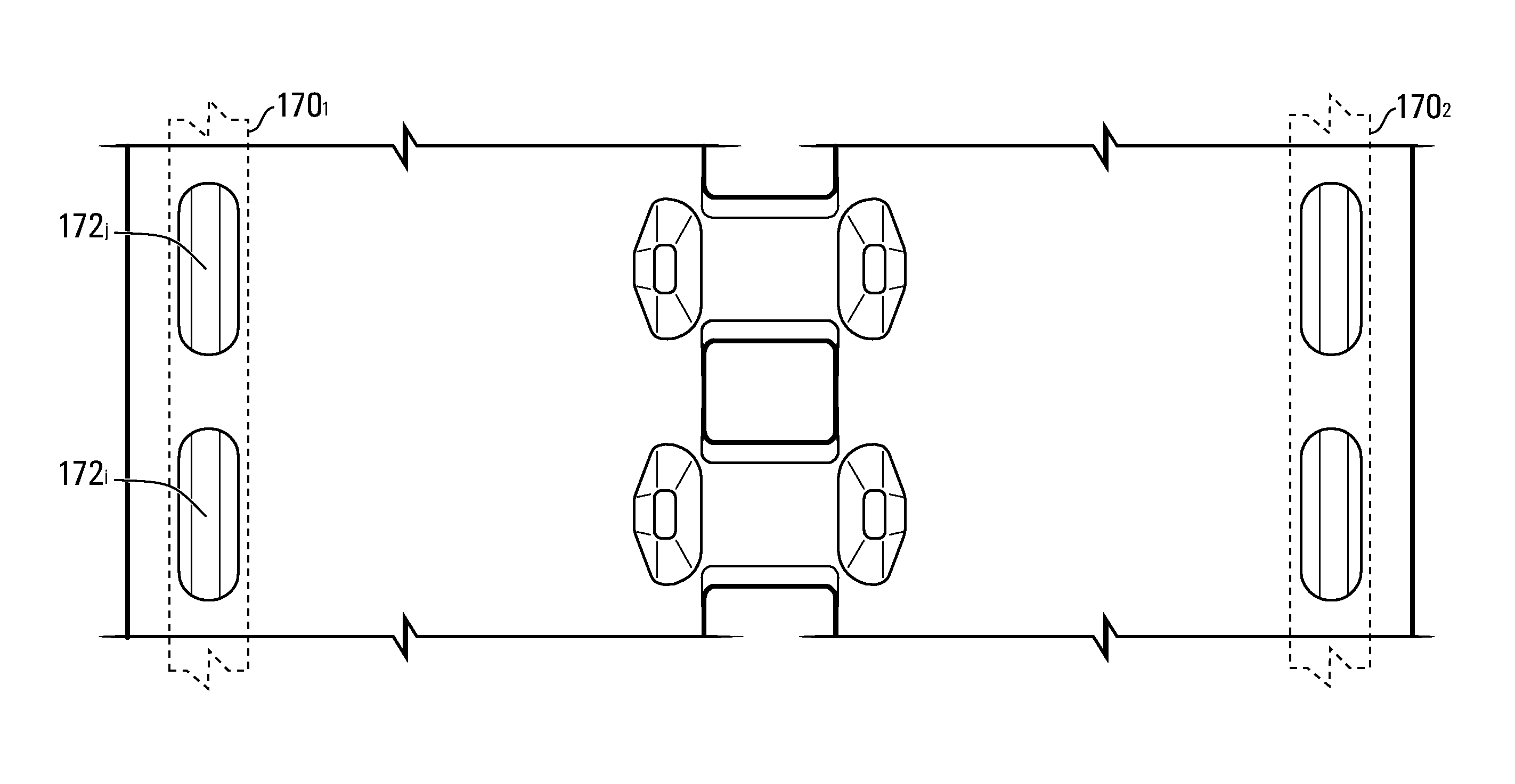
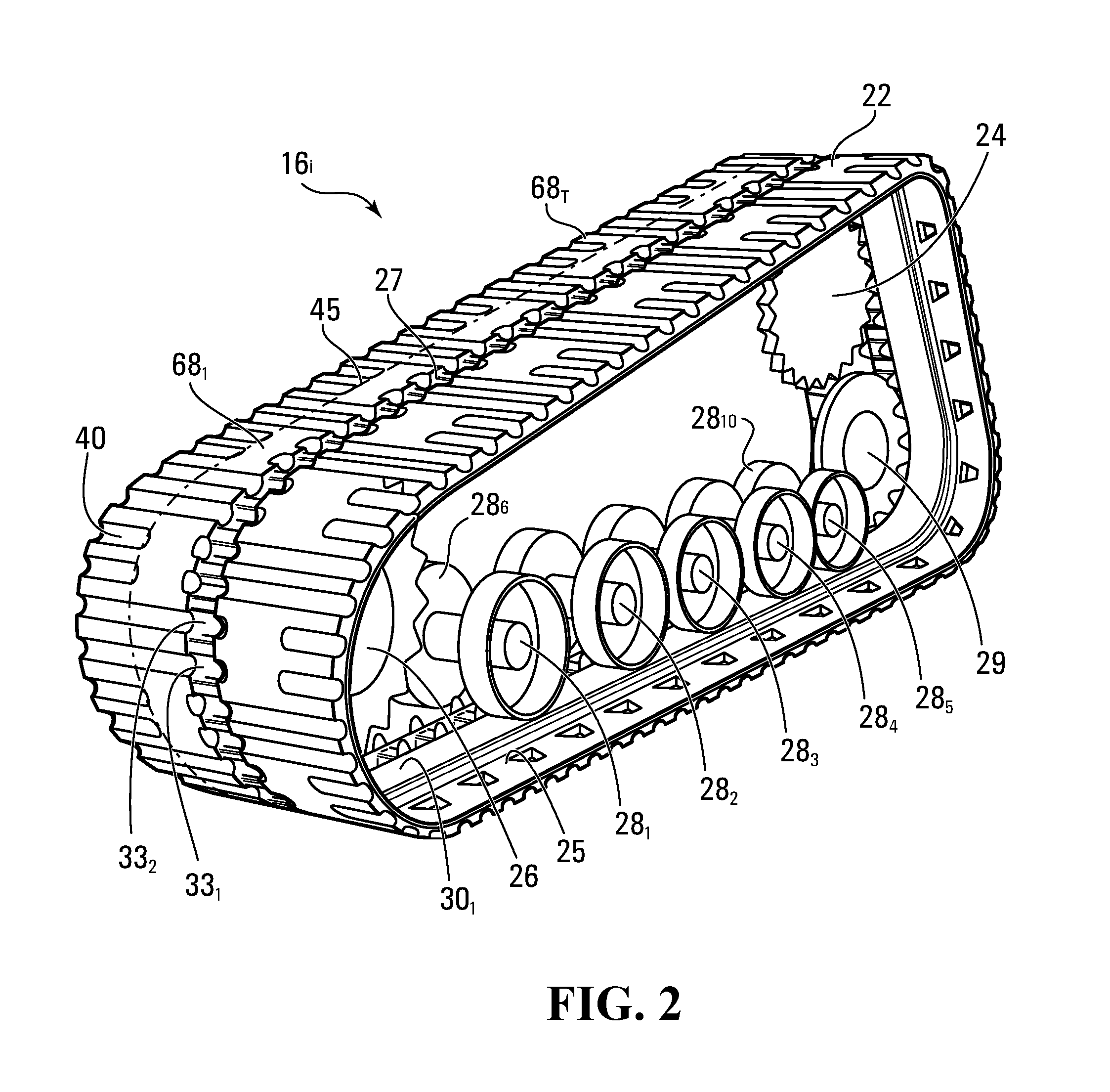
The invention offers an endless track for vehicles that provides traction. The track has a longitudinally extending elastomeric body with embedded cores that give it transverse rigidity. It also has impact absorbers at the edges to absorb impact and deformation. The track can have holes or deformable parts to further absorb impact or facilitate deformation. When the track comes into contact with an obstacle on the ground, it can flex and absorb the impact, ensuring a smooth ride for the vehicle.

Problems solved by technology

A problem often encountered with this type of endless track is that, when a lateral edge part of the track impacts an obstacle on the ground (e.g., a curb, a sidewalk, a rock, an abrupt change in ground level, etc.), the track may deform in such a way that some of its elastomeric material in its lateral edge part begins to tear.
Such tearing of the track's elastomeric material, which is referred to as “edge-cutting”, may cause premature deterioration of the track.
For example, sand, rocks, water and / or other undesirable matter may infiltrate the track through the tear and prematurely deteriorate the track (e.g., by leading to a progressive loss of adhesion between the elastomeric material and the cores and / or other components of the track).
In addition, the tear itself may reach a size that renders the track's performance and / or appearance unacceptable.

Method used


Image

  • Endless track for propelling a vehicle, with edge-cutting resistance
  • Endless track for propelling a vehicle, with edge-cutting resistance
  • Endless track for propelling a vehicle, with edge-cutting resistance

Examples


Embodiment Construction

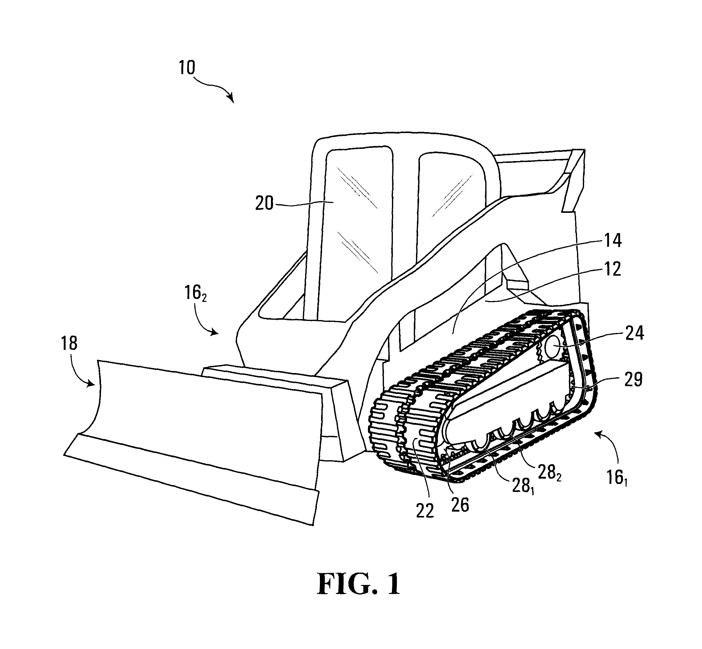
[0030]FIG. 1 shows a work vehicle 10 in accordance with an embodiment of the invention. In this embodiment, the work vehicle 10 is a construction vehicle designed to perform construction work. More specifically, in this example, the construction vehicle 10 is a loader. In other examples, the construction vehicle 10 may be a bulldozer, a backhoe loader, an excavator, or any other type of construction vehicle.

[0031]The construction vehicle 10 comprises a frame 12 supporting a prime mover 14, a pair of track assemblies 161, 162 (which can be referred to as “undercarriages”), and an operator cabin 20, from which an operator can control the construction vehicle 10 to move it on the ground and perform construction work using a working implement 18.

[0032]The prime mover 14 is a source of motive power to move the construction vehicle 10. For example, the prime mover 14 may comprise an internal combustion engine and / or one or more other types of motors (e.g., electric motors, etc.) for gener...


PUM


Abstract

An endless track for providing traction to a vehicle, such as a construction vehicle, an agricultural vehicle or other work vehicle. The endless track has: an inner side for facing a plurality of wheels of the vehicle; a ground-engaging outer side for engaging the ground; a first lateral edge; and a second lateral edge. The endless track comprises an elastomeric body and a plurality of cores at least partially embedded in the elastomeric body. Each core extends transversally to a longitudinal direction of the endless track to provide transverse rigidity to the endless track. The endless track comprises an impact absorber in a lateral edge part of the endless track, the lateral edge part being located between the cores and a given one of the first lateral edge and the second lateral edge. The impact absorber facilitates an elastic deformation of the lateral edge part when the lateral edge part impacts an obstacle on the ground. For example, in some embodiments, the impact absorber may comprise one or more holes which can deform when the lateral edge part impacts an obstacle on the ground.

Description

FIELD OF THE INVENTION[0001]The invention relates to endless tracks for propelling vehicles operable off-road, such as tracked work vehicles (e.g., construction vehicles, agricultural vehicles, forestry vehicles, etc.).BACKGROUND[0002]Certain off-road vehicles, including work vehicles such as construction vehicles (e.g., loaders, bulldozers, excavators, etc.), agricultural vehicles (e.g., harvesters, combines, tractors, etc.) forestry vehicles (e.g., feller-bunchers, tree chippers, knuckleboom loaders, etc.) and military vehicles (e.g., combat engineering vehicles (CEVs), etc.), are often equipped with endless tracks that enhance their traction and floatation on soft, low friction and / or uneven grounds (e.g., soil, mud, sand, ice, snow, etc.) on which they operate.[0003]One type of endless track comprises a body including elastomeric material (e.g., rubber) in which are embedded rigid cores (e.g., metallic cores) that extend transversally to impart transverse rigidity to the track a...

Claims


Application Information

Patent Timeline
Patent Type & Authority Patents(United States)
IPC IPC(8): B62D55/24
CPCB62D55/244B62D55/02B62D55/18B62D55/24
Inventor LAJOIE, HUGUESHAN, CHEOL HEEPARK, SUNG CHAN
Owner CAMOPLASY INC
Learn More