Harpoon head and corresponding harpoon

a technology of harpoon and corresponding harpoon, which is applied in the direction of emergency equipment, transportation and packaging, travelling objects, etc., can solve the problems of reducing the likelihood of the harpoon head coming into contact with the stop surface of the grating, and a significant cos

Active Publication Date: 2014-11-04
DCNS SA
View PDF25 Cites 2 Cited by
  • Summary
  • Abstract
  • Description
  • Claims
  • Application Information

AI Technical Summary

Problems solved by technology

Moreover, during use of the harpoon, the repetition of shocks between the harpoon head and the grating ends up dulling the distal end of the harpoon head.
In return, the presence of this end face increases the likelihood of the ha

Method used


Image

  • Harpoon head and corresponding harpoon
  • Harpoon head and corresponding harpoon
  • Harpoon head and corresponding harpoon

Examples


Embodiment Construction

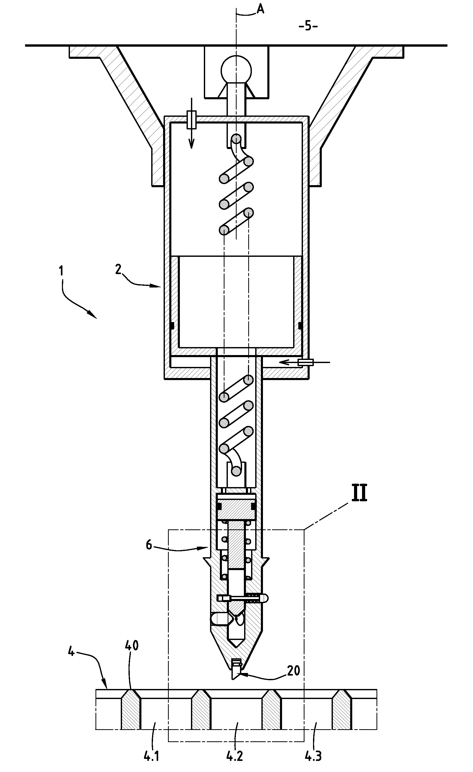
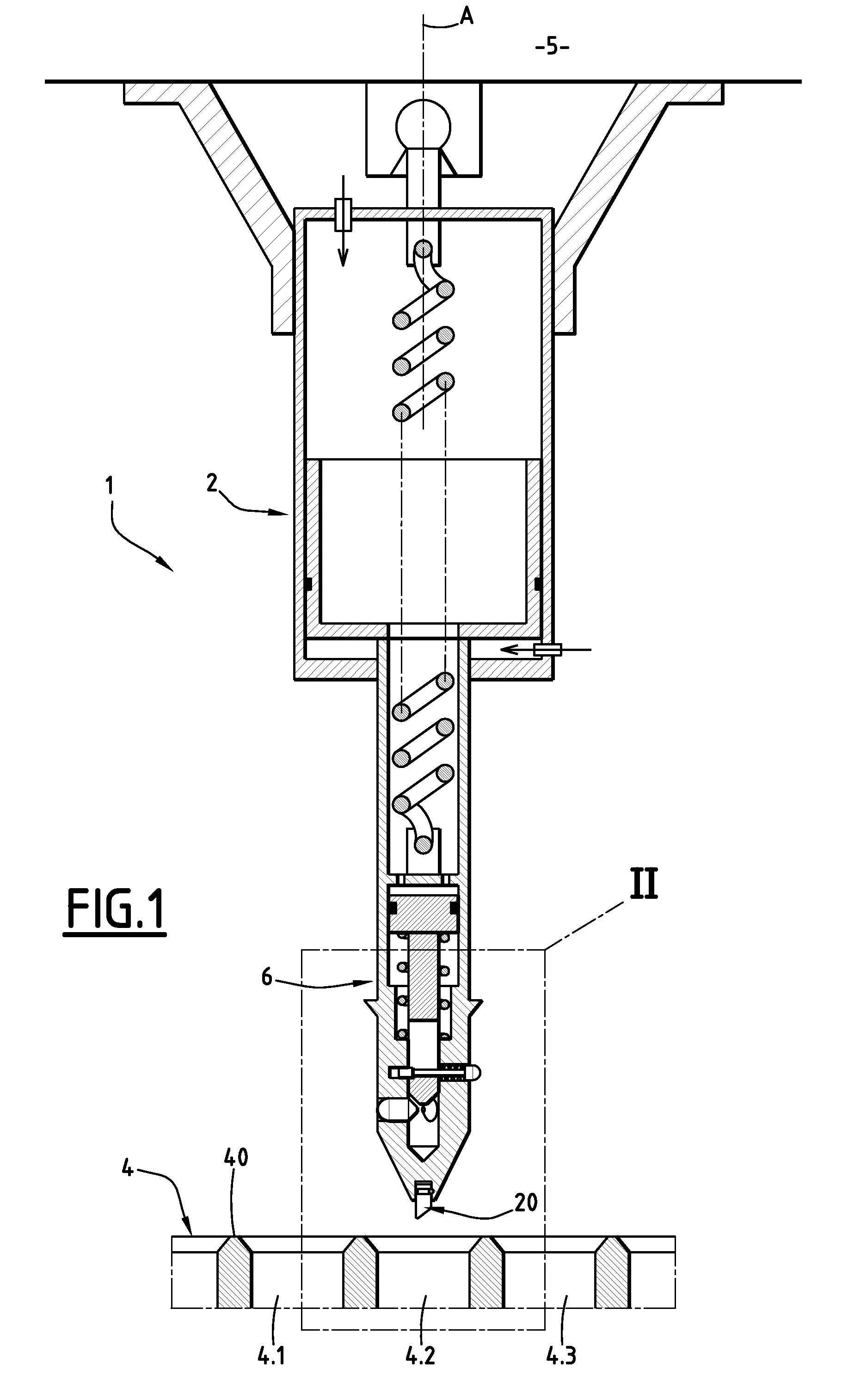
[0021]In reference to FIG. 1, a system 1 for anchoring an aircraft on a deck includes a harpoon 2 and a grating 4. The grating 4 has a planar upper surface including a plurality of cells 4.1, 4.2, 4.3. The harpoon 2 is positioned under the fuselage 5 of the aircraft, while the grating 4 is positioned on the pontoon on which the aircraft can land. The harpoon 2 has an oblong shape along an axis A. A distal end of the harpoon 2, situated away from the aircraft 5 carrying the harpoon 2, is provided with a harpoon head 6 capable of cooperating with a cell 4.1, 4.2, 4.3 of the grating 4, during the anchoring operation of the aircraft.

[0022]In order to immobilize the aircraft on the deck, the harpoon is fired after the approach phase, once the aircraft comes back into contact with the deck.

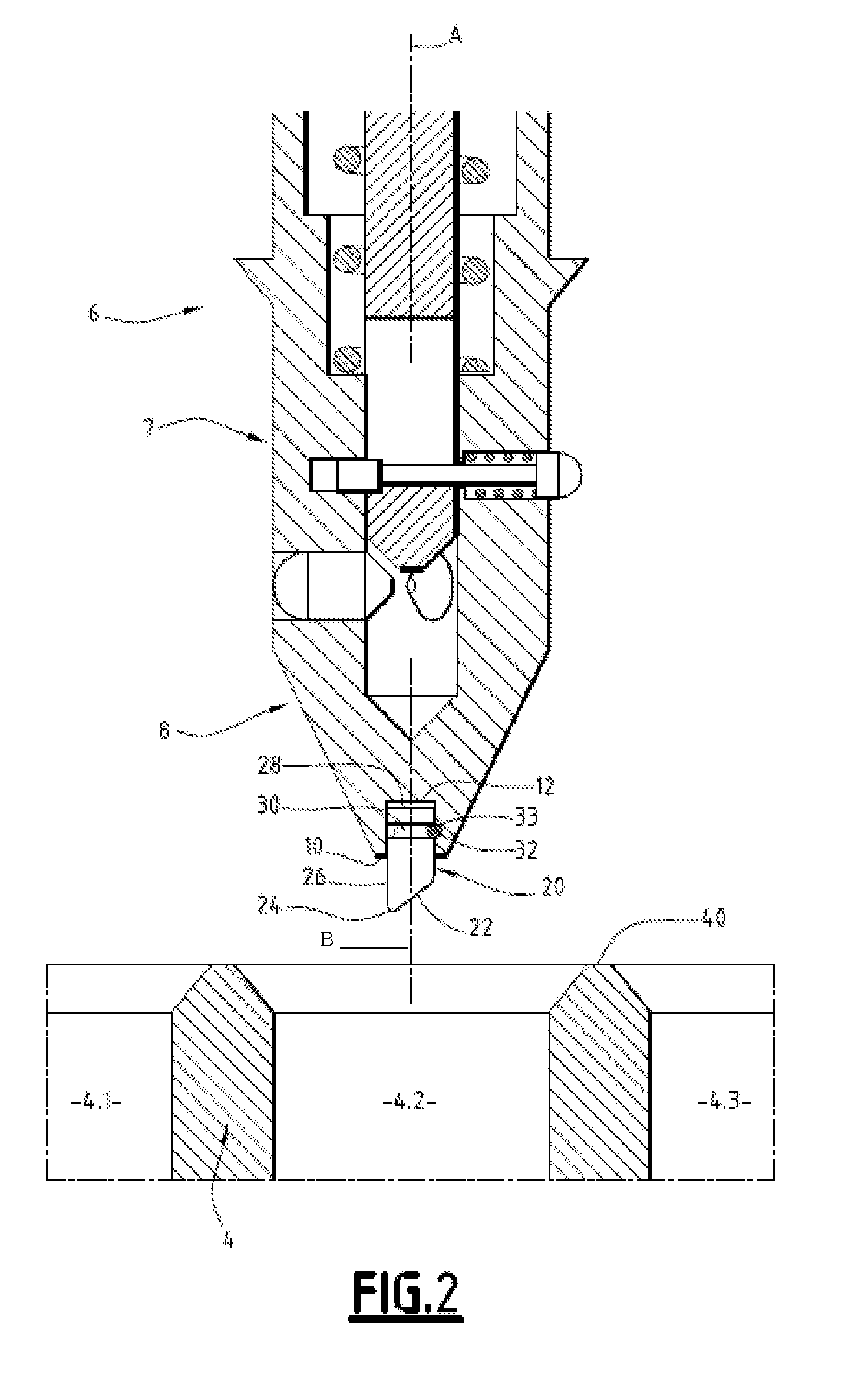
[0023]The harpoon head 6 becomes housed in one of the cells of the grating 4. At that moment, an anchoring means is actuated to prevent the withdrawal of the harpoon head 6 from the cell. Thus anchored,...


PUM


Abstract

A harpoon head (6) for a system for anchoring an aircraft on a grating (4) is characterized in that a distal end of the harpoon head has an interchangeable insert (20).

Description

BACKGROUND OF THE INVENTION[0001]1. Field of the Invention[0002]The present invention relates to a system for anchoring an aircraft on a grating. More particularly, the invention relates to an anchoring system of the type including a harpoon carried by the aircraft and actuated so that a harpoon head becomes anchored in a cell of the grating.[0003]2. Description of the Related Art[0004]Document FR 2 701 689 A1 describes a harpoon equipping an aircraft and able to be pulled towards a landing grating of the aircraft so that the head of the harpoon is fastened on the grating and forms an anchoring point of the aircraft, facilitating the landing operation of the aircraft. According to this document, the harpoon head includes a cylindrical central portion of axis A, and a conical end portion. The central portion includes fingers radially oriented and radially movable between a retracted position and an extended position. The harpoon head also includes means for driving the fingers and ke...

Claims


Application Information

Patent Timeline
IPC IPC(8): B64F1/26B64F1/12
CPCB64F1/125
Inventor PROUTIERE, SEVERINE
Owner DCNS SA
Why Eureka
Try Eureka