
Dispersion-engineered traveling wave kinetic inductance parametric amplifier

a parametric amplifier and dispersion-engineered technology, applied in the direction of amplifier types, variable-induction element amplifiers, amplifiers, etc., can solve the problems of noise performance, quantum mechanics limited noise performance, and the inability to produce excess noise,

Active Publication Date: 2014-11-04
CALIFORNIA INST OF TECH
View PDF4 Cites 19 Cited by
  • Summary
  • Abstract
  • Description
  • Claims
  • Application Information

AI Technical Summary

Problems solved by technology

Because the amplification mechanism relies on a nonlinear reactance, the device need not produce thermal noise or shot noise, and by the early 1960s it was understood that in principle, the noise performance is limited only by quantum mechanics.
In practice, varactor diodes are not ideal and do produce some excess noise, but nevertheless excellent noise performance can be obtained.
However, this noise performance is still a factor of ˜20 above the quantum mechanical limit hν / kB≈48 mK / GHz, and is inadequate for some demanding applications.
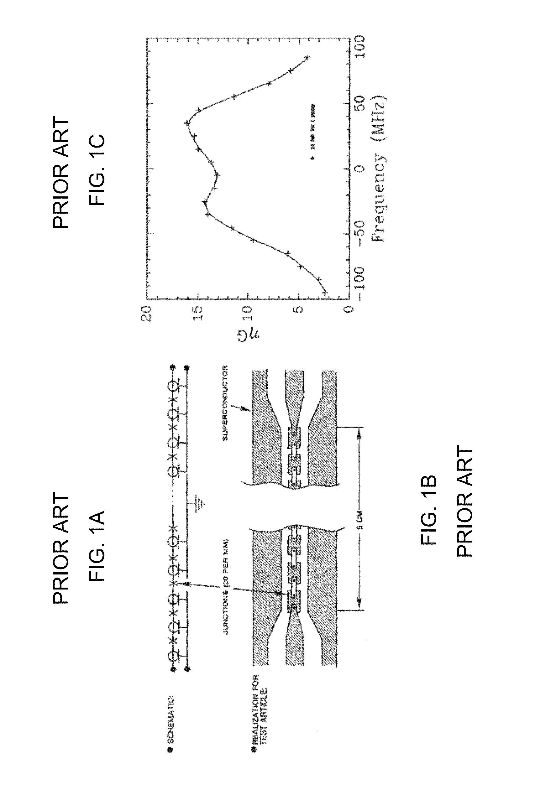
If properly designed, interactions between the pump and signal waves propagating along this structure could lead to amplification of the signal.
Landauer argued that traveling-wave amplifiers would be crippled by this effect: shock wave formation would prevent the amplifiers from achieving the desired combination of high gain with low noise.
Judging from the literature, Landauer's work appears to have substantially dampened the enthusiasm for traveling-wave parametric amplifiers operating at microwave frequencies in the subsequent decades.
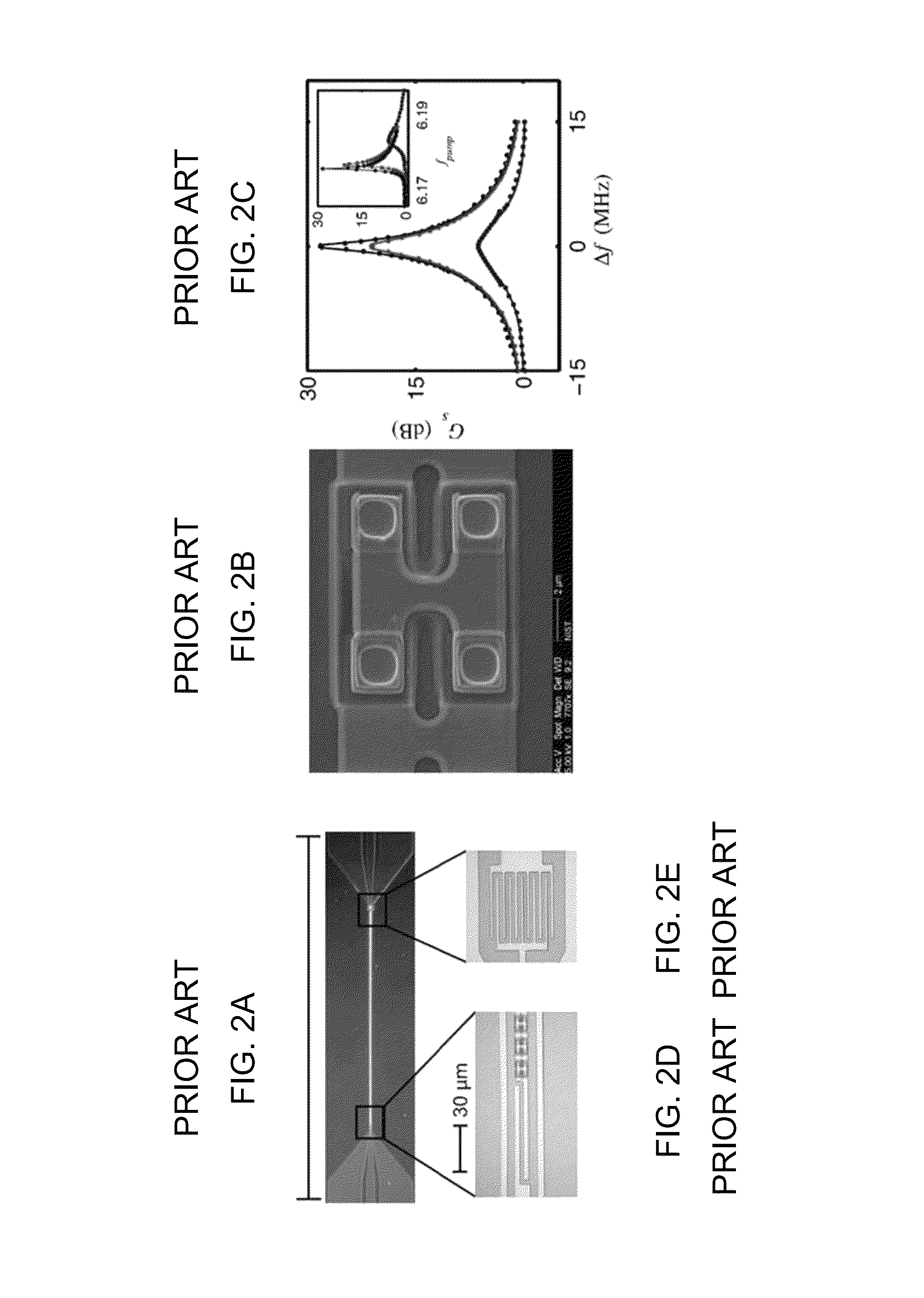
However, optical fiber parametric amplifiers did not receive much attention for decades, until 2001 when Hansryd and Andrekson demonstrated experimentally that, by using the dispersive characteristics of the fiber to advantage, very high gain was in fact possible in a fiber parametric amplifier.
However, for large currents approaching the critical value, the response is expected to become nonlinear, as discussed theoretically by Parmenter in 1962.
However, Connell focused his attention on standing-wave transmission-line resonators, as suggested and patented by Landauer (U.S. Pat. No. 3,111,628); presumably the shock-wave issue deterred serious consideration of the traveling-wave version.
This narrow bandwidth meant that the device had little practical value beyond a basic demonstration, and while the topic continued to receive theoretical attention on occasion, the focus of experimental work shifted to other more promising directions.
0 MHz. The input and output impedance match for this particular device was poor, so it was likely operating in a partial standing-wav

Method used


Image

  • Dispersion-engineered traveling wave kinetic inductance parametric amplifier
  • Dispersion-engineered traveling wave kinetic inductance parametric amplifier
  • Dispersion-engineered traveling wave kinetic inductance parametric amplifier

Examples


Embodiment Construction

DTWKI Amplifier Characteristics

[0062]We describe a new superconducting amplifier with exceptional performance, closely approaching the limits imposed by fundamental physics. We refer to this device as the Dispersion-engineered Traveling-Wave Kinetic Inductance (DTWKI) amplifier. Versions of this device may be implemented for operation in the microwave, millimeter-wave, and sub-millimeter-wave bands. The basic characteristics are demonstrated to be, or are expected to be, as we now describe.

[0063]The amplifier is expected to have extremely low noise and should operate very close to the fundamental limits imposed by quantum mechanics. At frequency f, this limit corresponds to a noise temperature of TQL=hf / kB, where h and kB are Planck's and Boltzmann's constants, respectively. Numerically, h / kB≈48 mK / GHz. For comparison, modern low-noise transistor amplifiers operating at cryogenic temperatures offer noise temperatures of order 1 K / GHz.

[0064]The gain bandwidth may be extremely wide, w...


PUM


Abstract

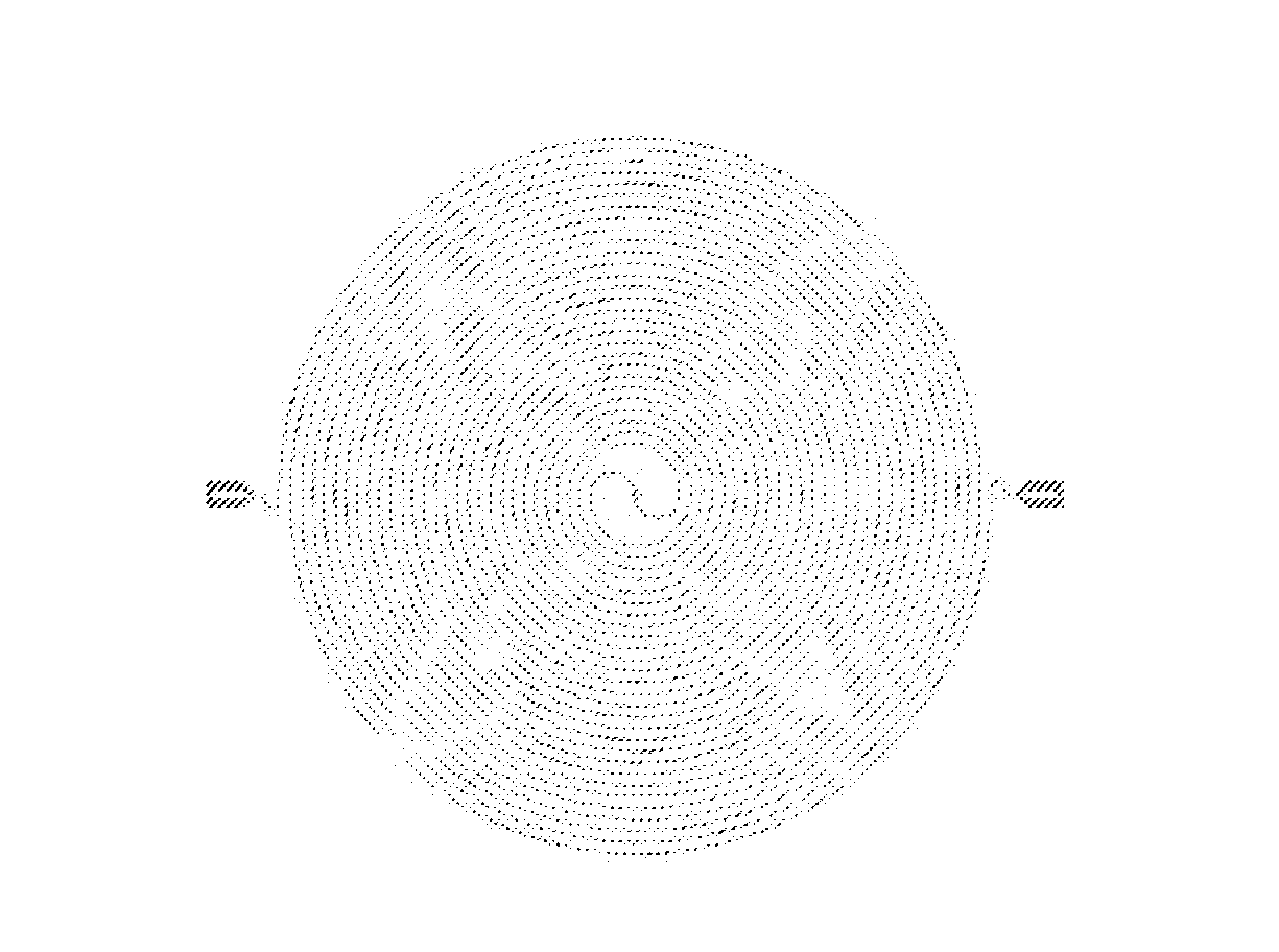
A traveling wave kinetic inductance parametric amplifier comprises a superconducting transmission line and a dispersion control element. The transmission line can include periodic variations of its dimension along its length. The superconducting material can include a high normal state resistivity material. In some instances the high normal state resistivity material includes nitrogen and a metal selected from the group consisting of titanium, niobium and vanadium. The traveling wave kinetic inductance parametric amplifier is expected to exhibit a noise temperature below 100 mK / GHz.

Description

CROSS-REFERENCE TO RELATED APPLICATIONS[0001]This application claims priority to and the benefit of U.S. provisional patent application Ser. No. 61 / 394,848 filed Oct. 20, 2010, which application is incorporated herein by reference in its entirety.STATEMENT REGARDING FEDERALLY FUNDED RESEARCH OR DEVELOPMENT[0002]This invention was made with government support under NNX10AC83G awarded by NASA. The government has certain rights in the invention.FIELD OF THE INVENTION[0003]The invention relates to traveling-wave parametric amplifiers.BACKGROUND OF THE INVENTION[0004]Traveling-wave parametric amplifiers, first proposed in the late 1950s, rely on the use of a low-loss nonlinear material. Although originally envisioned as electrical amplifiers operating at radio or microwave frequencies, the traveling-wave parametric amplifier concept was later adapted for use at optical frequencies and versions using optical fibers have now been successfully demonstrated. Relevant descriptions of those te...

Claims


Application Information

Patent Timeline
Patent Type & Authority Patents(United States)
IPC IPC(8): H03F19/00H03F7/00H03F7/02
CPCH03F7/02
Inventor ZMUIDZINAS, JONASDAY, PETER K.
Owner CALIFORNIA INST OF TECH
Learn More