DSA suspension with microactuators extending to gimbal through flexible connectors

a microactuator and suspension technology, applied in the direction of instruments, record information storage, support for heads, etc., can solve the problems of catastrophic head crash, fretting wear, etc., and achieve good shock susceptibility, good stroke length, and high servo bandwidth

Active Publication Date: 2014-11-04
MAGNECOMP
View PDF57 Cites 37 Cited by
  • Summary
  • Abstract
  • Description
  • Claims
  • Application Information

AI Technical Summary

Benefits of technology

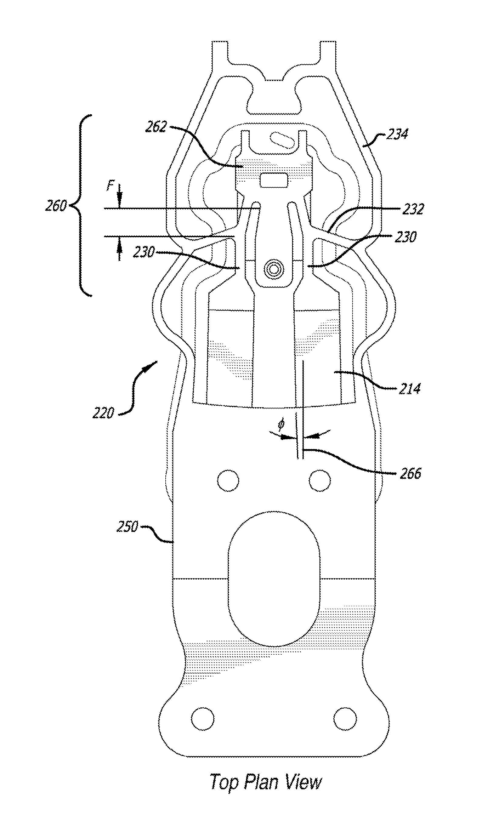
[0012]The present invention is of a DSA suspension have one or more PZTs that extend from the load beam, or more generally from a non-gimbaled portion of the suspension, and more specifically from a non-gimbaled or rigid portion of the flexure, to a gimbaled part of the suspension such as the slider tongue. The PZTs are connected to the gimbaled portion through thin ribbons of stainless steel and/or other materials that act as flexible connectors to transmit tensile and compressive forces, and thereby transmit push/pull movement of the PZTs, to the gimbaled portion to which the head slider is attached, the connectors being f...

Problems solved by technology

This greatly decreases fretting wear on the dimple, which is of concern because fretting of the dimple pro...

Method used


Image

  • DSA suspension with microactuators extending to gimbal through flexible connectors
  • DSA suspension with microactuators extending to gimbal through flexible connectors
  • DSA suspension with microactuators extending to gimbal through flexible connectors

Examples


Embodiment Construction

[0025]For discussion purposes, the present disclosure will refer to the microactuator as being “PZTs,” although it will be understood that other types of microactuators could be used as well, and thus the invention is applicable to DSA suspensions using other types of micro actuators.

[0026]FIG. 3 is an oblique, partially exploded view of a DSA suspension according to an illustrative embodiment of the invention. Suspension 205 includes base plate 212, load beam 207, a flexure 220 welded or otherwise affixed to the load beam, and magnetic read / write head slider 240 affixed to the distal and gimbaled portion of flexure 220. For purposes of the present discussion, load beam 207 and the portion of flexure 220 rigidly affixed to load beam 207 will be referred to as being rigid or non-gimbaled.

[0027]FIG. 4 is a top plan view of the flexure 220 of the suspension of FIG. 3, viewed from what is sometimes referred to as the “gimbal top,” and FIG. 5 is a bottom plan view of the flexure 220 of t...


PUM


Abstract

A dual stage actuated (DSA) suspension includes two PZT microactuators that are attached at their first ends to a non-gimbaled portion of the suspension such as the portion of the flexure that is rigidly attached to the load beam, and are attached at their second ends to the gimbaled portion of the suspension such as the gimbal tongue through flexible connectors that can be formed integrally with the suspension's flexure. The flexible connectors are flexible enough so as not to interfere with the suspension's gimballing action. The flexible connectors transmit force from the PZTs to the gimbal as the PZTs expand and contract in order to rotate the gimbal and thus effect fine movements of the head slider.

Description

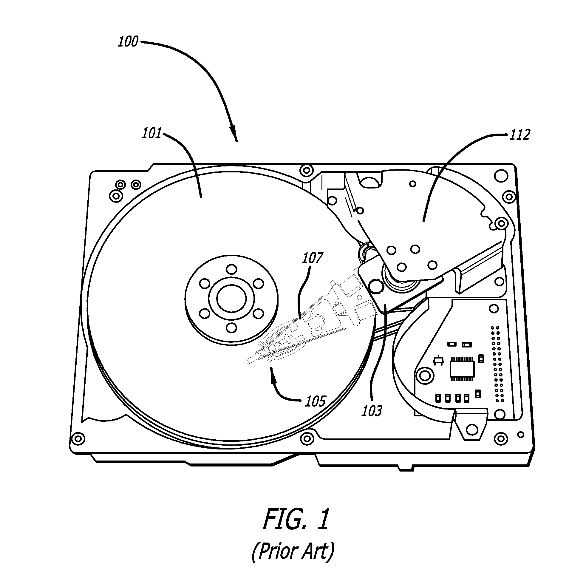
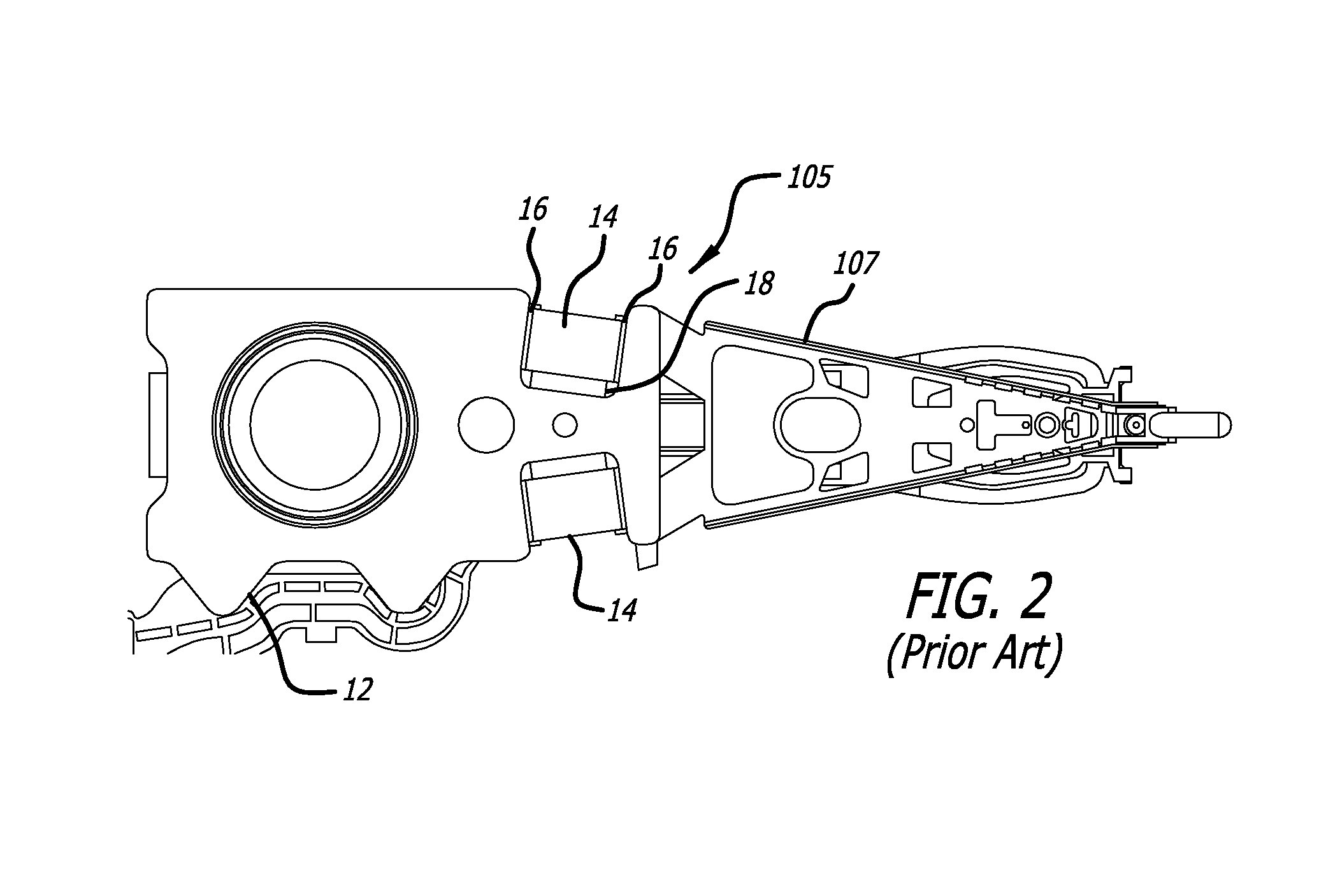
CROSS-REFERENCE TO RELATED APPLICATIONS[0001]This application claims benefit of U.S. Provisional Patent Application No. 61 / 535,349 filed Nov. 30, 2011, which is hereby incorporation by reference as if set forth fully herein.BACKGROUND OF THE INVENTION[0002]1. Field of the Invention[0003]This invention relates to the field of dual stage actuator (DSA) type suspensions for disk drives including hard disk drives. More particularly, this invention relates to the field of a dual stage actuator suspension in which the microactuators are connected to the gimbaled region through flexible connectors.[0004]2. Description of Related Art[0005]Magnetic hard disk drives and other types of spinning media drives such as optical disk drives are well known. FIG. 1 is an oblique view of an exemplary prior art hard disk drive and suspension for which the present invention is applicable. The prior art disk drive unit 100 includes a spinning magnetic disk 101 containing a pattern of magnetic ones and zer...

Claims


Application Information

Patent Timeline
IPC IPC(8): G11B5/48G11B21/21
CPCG11B21/21G11B5/4873G11B5/482G11B5/483G11B5/4833G11B5/53
Inventor HAHN, PETEREE, KUEN CHEEZHANG, LONG
Owner MAGNECOMP
Why Eureka
Try Eureka