Pivoting axle system

a technology of pivoting axles and supporting structures, which is applied in the direction of lifting devices, transportation and packaging, bicycles, etc., can solve the problem of limited transportation of wider wheel bases

Active Publication Date: 2014-11-18
JLG IND INC
View PDF6 Cites 27 Cited by
  • Summary
  • Abstract
  • Description
  • Claims
  • Application Information

AI Technical Summary

Problems solved by technology

A wider wheel base also provides added stability, but a wider wheel base has limitations for transport since a width of the more stable wheel base typically exceeds maximum limitations for transport or on-road travel.

Method used


Image

  • Pivoting axle system
  • Pivoting axle system
  • Pivoting axle system

Examples


Embodiment Construction

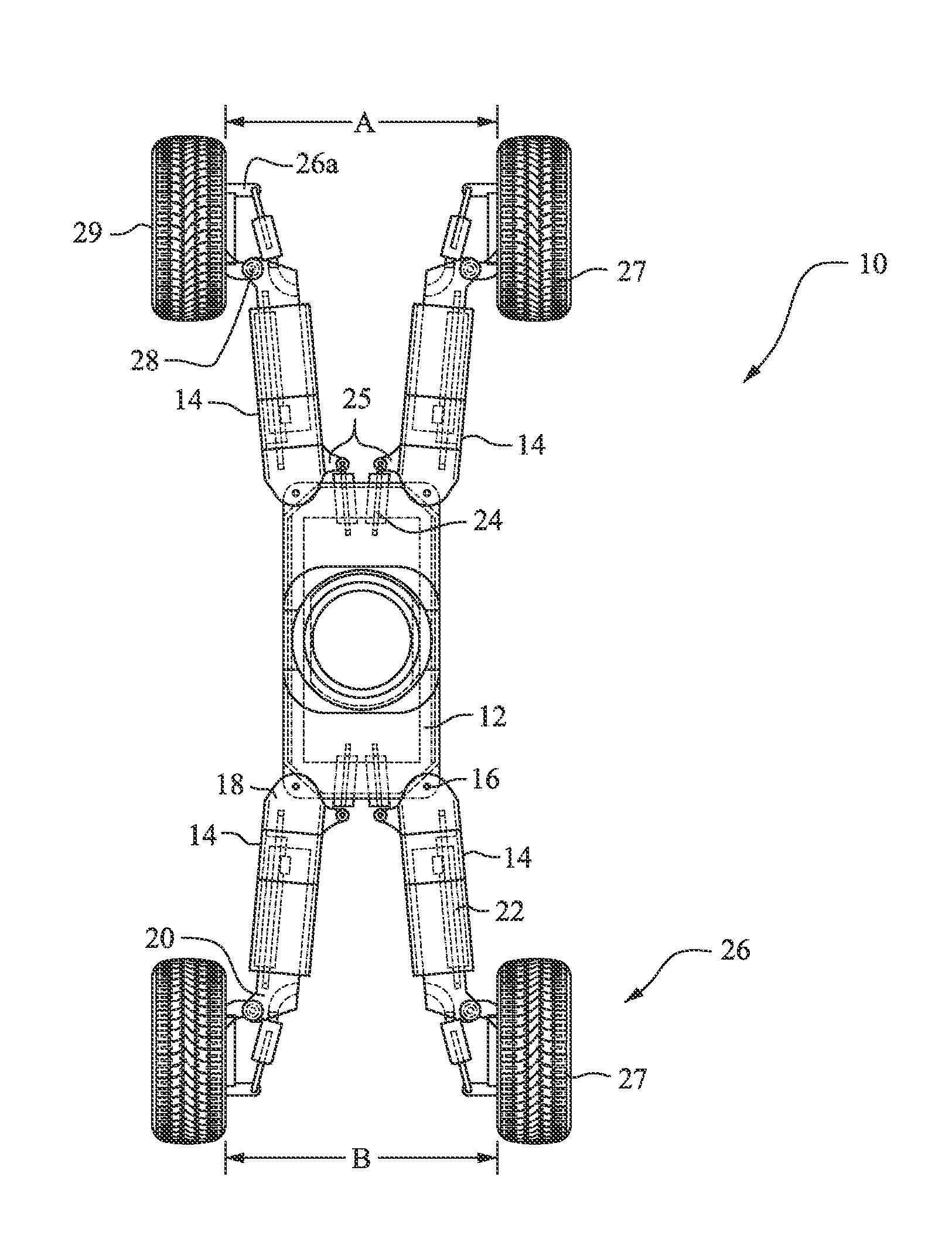
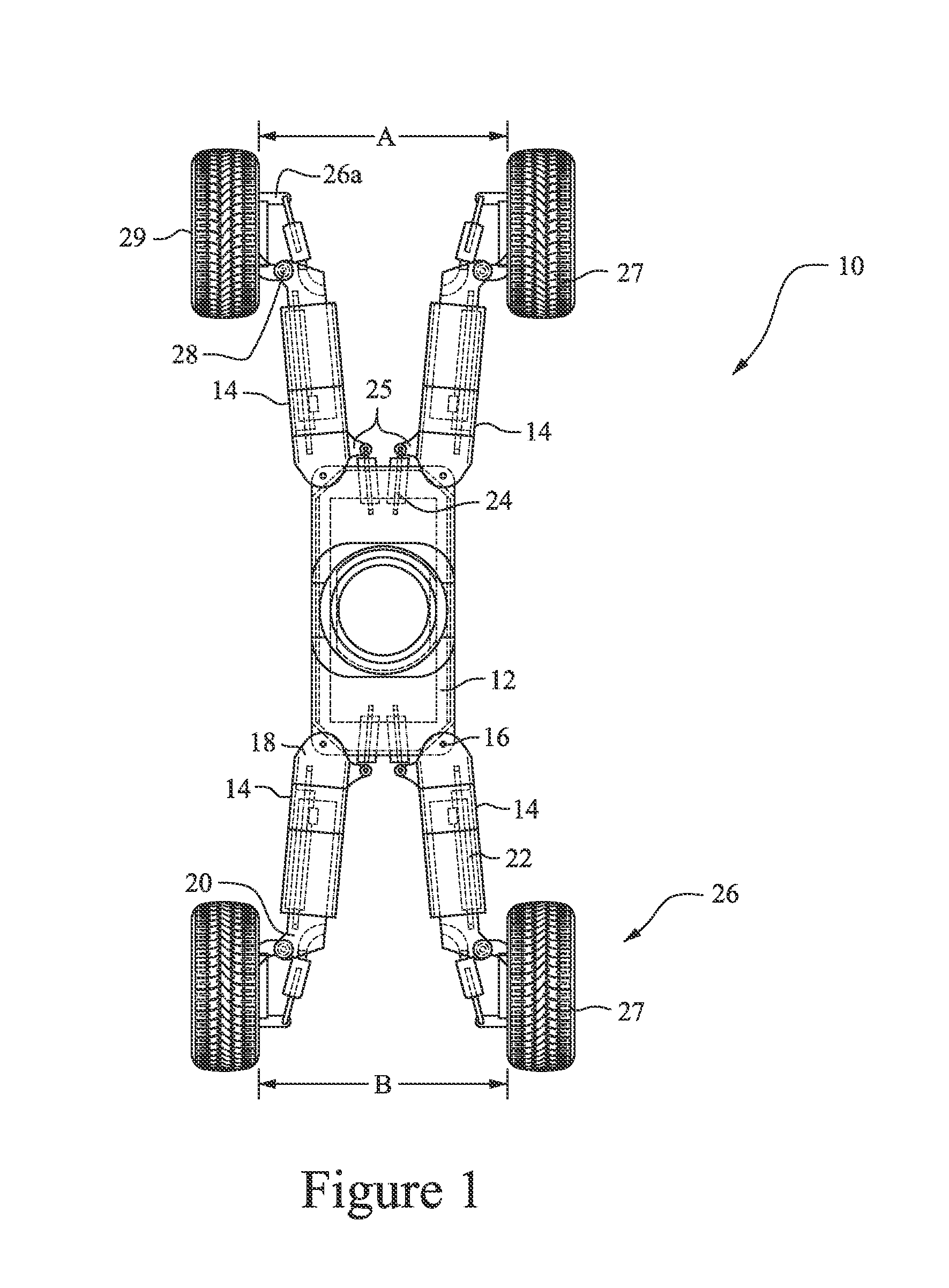
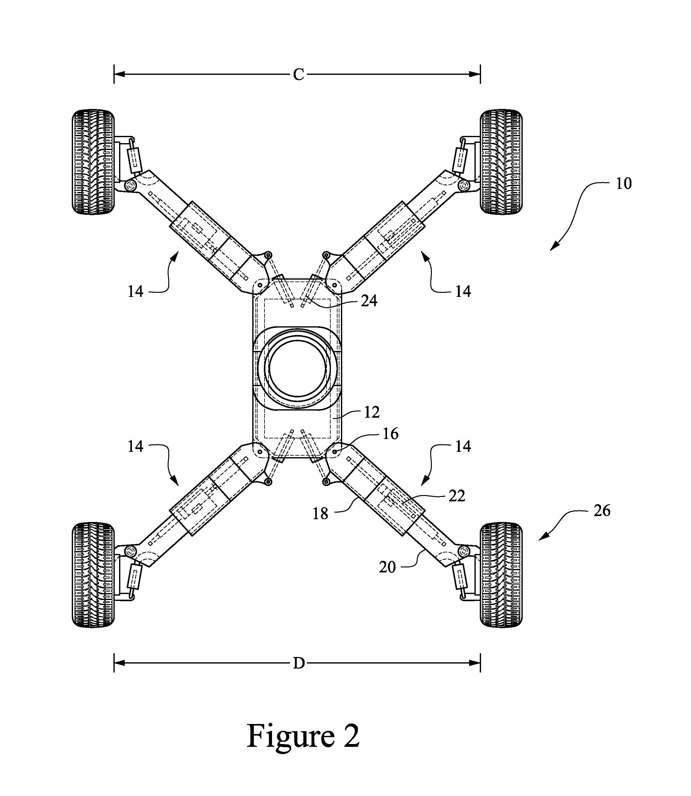
[0017]FIG. 1 shows a chassis assembly according to preferred embodiments of the invention in the stowed position, and FIG. 2 shows the chassis assembly in the working position. The chassis assembly 10 includes a chassis 12 and four independently controllable axles 14, including a pair of front axles and a pair of rear axles. Each of the axles 14 is pivotally secured to the chassis 12 via a pivot connection 16. Each axle 14 is independently controllable (i.e., separately operable), and the respective axles 14 are not connected to one another. Actuators 24 are connected between the chassis 12 and each of a plurality of axles 14, respectively. As shown in the drawings, the actuators 24 are connected to the chassis 12 at positions spaced from the pivot points 16. Actuator brackets 25 are connected to each of the plurality of axles 14, respectively. The actuators 24 are connected between the chassis 12 and respective connecting points of the actuator brackets 25. As shown, the connecting...


PUM


Abstract

A pivoting axle system for an aerial lift vehicle includes a plurality of axles pivotally secured to the vehicle chassis at respective pivot points between a stowed position and a working position. Each axle is coupleable with a wheel assembly at distal ends thereof. Actuators are connected between the chassis and each of the plurality of axles, respectively, where the actuators are connected to the chassis at positions spaced from the pivot points, respectively. Additionally, each of the plurality of axles is independently controllable.

Description

CROSS-REFERENCES TO RELATED APPLICATIONS[0001]This application claims the benefit of U.S. Provisional Patent Application Ser. No. 61 / 612,597, filed Mar. 19, 2012, the entire content of which is herein incorporated by reference.STATEMENT REGARDING FEDERALLY SPONSORED RESEARCH OR DEVELOPMENT[0002](Not Applicable)BACKGROUND OF THE INVENTION[0003]The invention relates to a boom lift product and, more particularly, to supporting structure for a boom lift product that is expandable and retractable between a stowed / transport position and a working position.[0004]It is desirable with a boom lift product to provide a stable and secure base when a platform supported at an end of an extendible boom is used in a raised position. Stability can be achieved through the use of outriggers, counterweights and the like. A wider wheel base also provides added stability, but a wider wheel base has limitations for transport since a width of the more stable wheel base typically exceeds maximum limitations...

Claims


Application Information

Patent Timeline
Patent Type & Authority Patents(United States)
IPC IPC(8): B66F9/075B60G7/00B66C23/62B60B35/10B60G3/02
CPCB60Y2200/15B66F9/07522B60G2300/40B60B35/1054B60B35/10B60G3/02B60G7/00B66C23/62
Inventor BERRY, DAVE
Owner JLG IND INC
Why Eureka
Try Eureka