Mounting brace assembly for mounting an electrical box

a brace and mounting bracket technology, applied in the direction of cable termination, installation of lighting conductors, coupling device connections, etc., can solve the problems of awkward installation of braces and lack of support, and achieve the effect of strong and rigid structure and efficient production

Active Publication Date: 2014-11-18
HUBBELL INC
View PDF29 Cites 25 Cited by
  • Summary
  • Abstract
  • Description
  • Claims
  • Application Information

AI Technical Summary

Benefits of technology

[0013]A further feature of the invention is to provide a brace assembly that can be mounted to a T-bar shaped ceiling support or ceiling grid used for a suspended ceiling where the brace assembly includes a hanger member that can be coupled to a secondary support for increasing the load capabilities of the assembly. The brace can have indicia to identify a load rating of the brace and the electrical box. The hanger member and / or the rear wall of the electrical box can have a window or other opening that aligns with the indicia so that the load rating is visible after installation of the hanger member on the brace.
[0016]Another feature of the invention is to provide a brace made from a single sheet of steel that is folded to form a substantially inverted T-shape. The brace has a pair of parallel side walls forming a longitudinal cavity. Outwardly extending legs have a hollow interior that forms a longitudinal channel between the legs to receive a mounting bar and mounting screws from the electrical box to couple the electrical box to the brace. A slot is formed in the bottom side that enables the electrical box, mounting screws and mounting bar to slide along the length of the brace. The shape of the brace provides a very strong and rigid structure that can be made efficiently from a sheet metal blank.

Problems solved by technology

Such braces can be awkward to install and may not provide the needed support for the intended device to be mounted to the electrical box.

Method used


Image

  • Mounting brace assembly for mounting an electrical box
  • Mounting brace assembly for mounting an electrical box
  • Mounting brace assembly for mounting an electrical box

Examples


Embodiment Construction

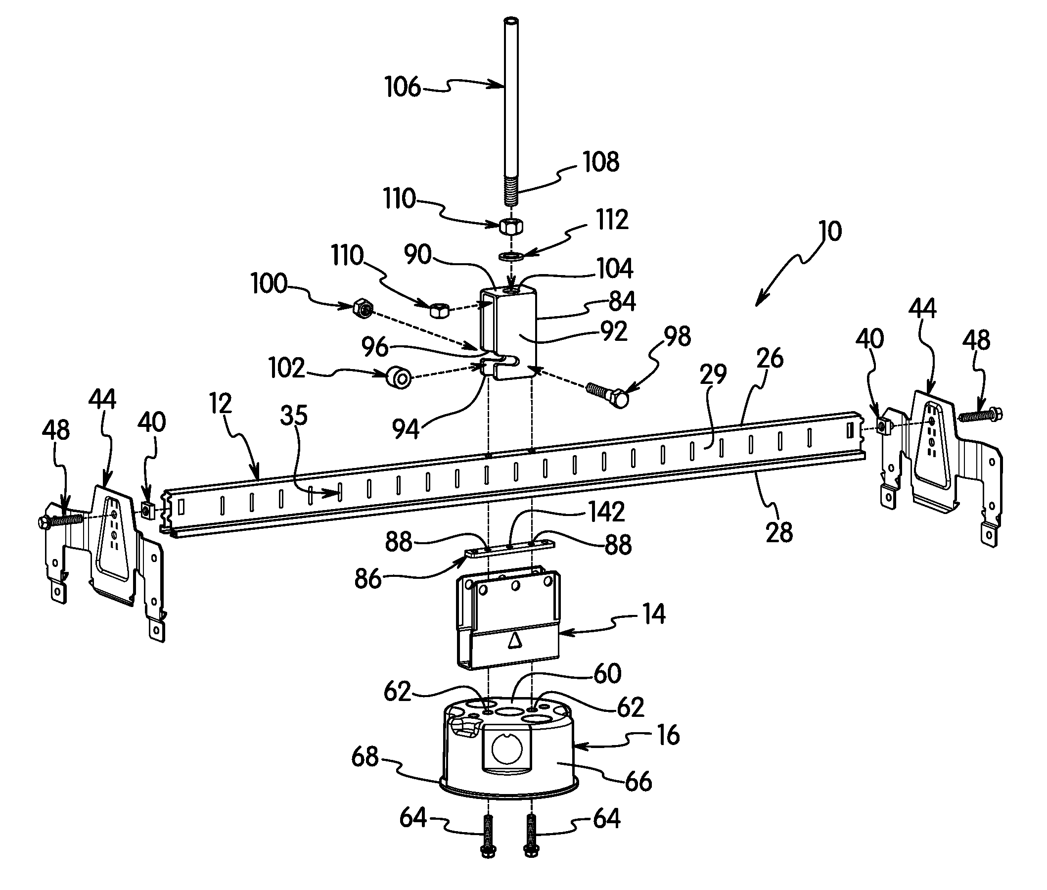
[0042]The present invention is directed to a brace assembly adapted for coupling to an overhead support and for supporting an electrical box. The invention is particularly directed to a brace assembly for mounting to a ceiling bar support and to a secondary support member to support the electrical box.

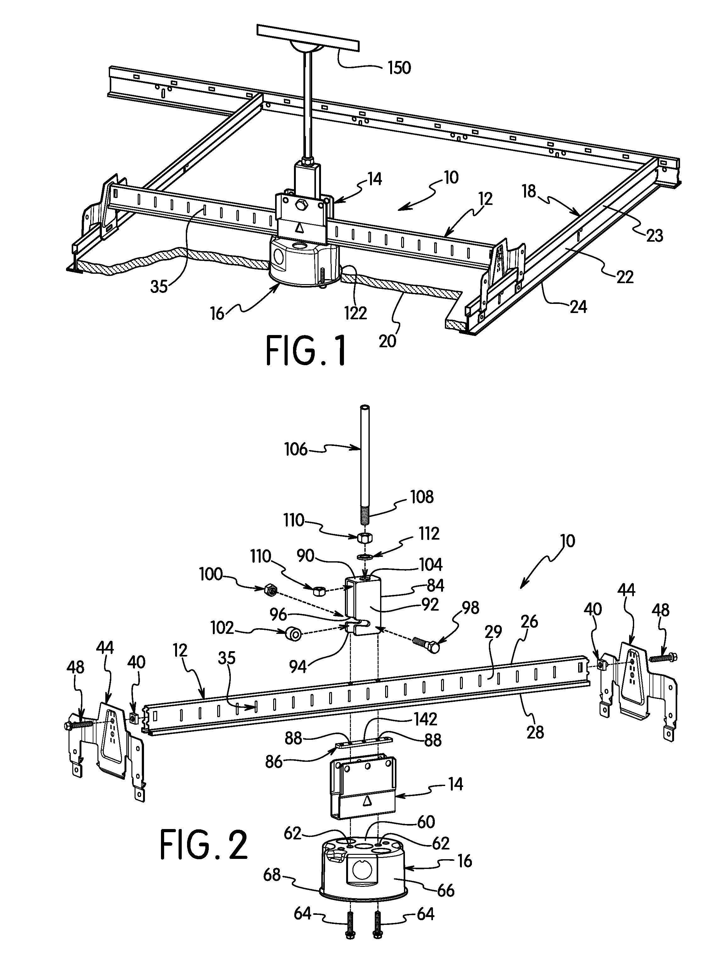
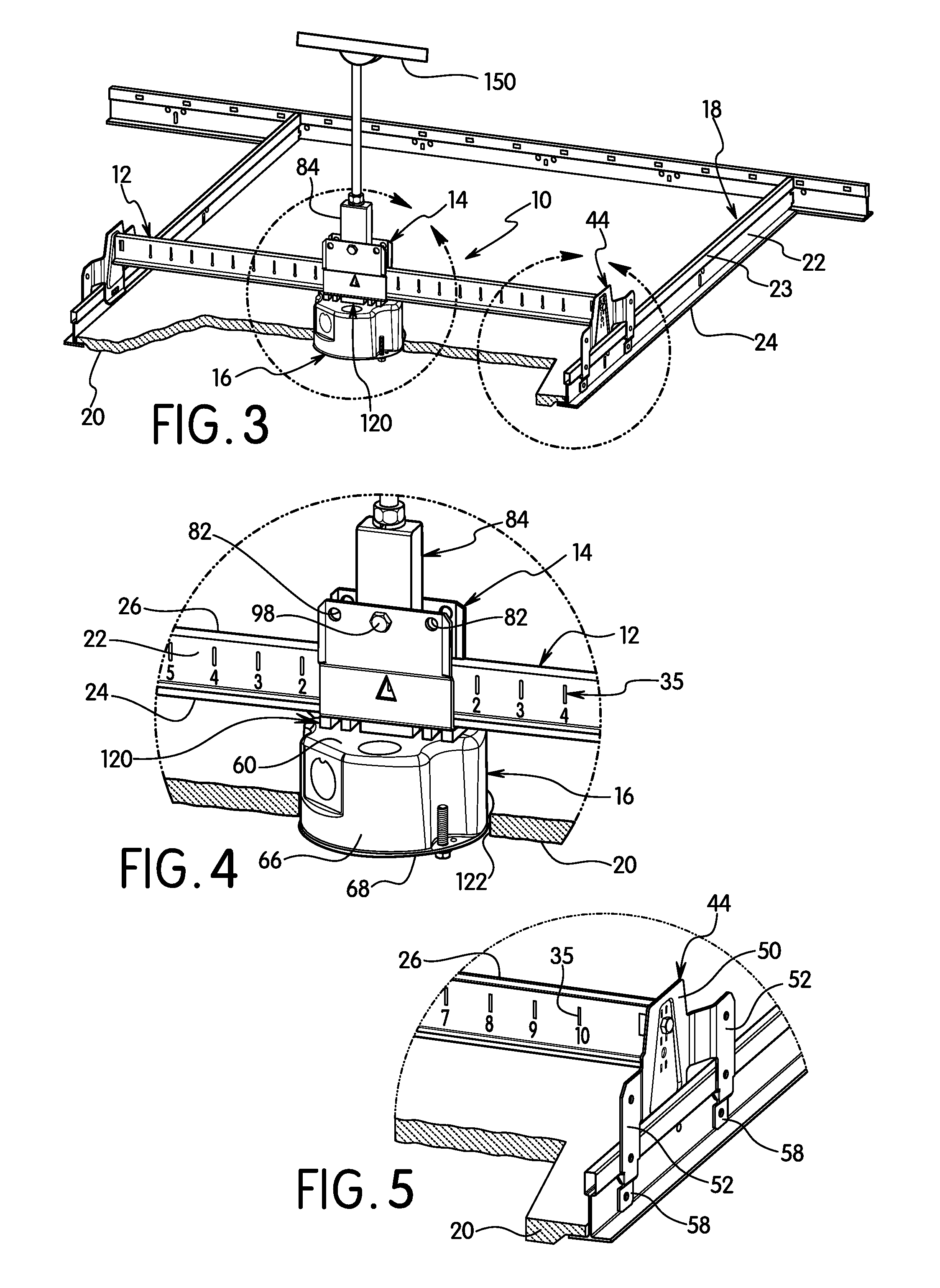
[0043]Referring to the drawings, the brace assembly 10 of the present invention includes a brace 12, a hanger member 14, and an electrical box 16. The brace assembly 10 is adapted for mounting the electrical box 16 and supporting the weight of an electrical fixture, such as a ceiling fan, luminaire or other electrical device. The brace 10 assembly is particularly directed to an assembly that can be coupled and mounted to a ceiling bar support 18 commonly used for suspended ceiling tiles 20. The ceiling bar support 18 is attached to the walls and / or ceiling above the living area of the building as known in the art.

[0044]The ceiling bar support 18, as known in the art, generally has a su...


PUM


Abstract

A brace assembly is provided having a brace for mounting to a support and a hanger member. The hanger member is coupled to the brace by a bar positioned in a longitudinal slot in the bottom side of the brace. The bar enables the hanger member to slide along the length of the brace. The hanger member has a bottom wall and side walls with a top end for coupling to a support. A mounting bracket is removably coupled to the hanger member for supporting the brace.

Description

FIELD OF THE INVENTION[0001]The present invention is directed to a mounting brace assembly for an electrical box. The invention is particularly directed to a brace assembly for attaching to a first ceiling support and having a mounting bracket for suspending the brace from a second support.BACKGROUND OF THE INVENTION[0002]Ceiling fan and support braces for ceiling fans and luminaires are known for the support various outlet boxes. The braces are typically installed between supports such as trusses and joists in the ceiling or other overhead structures. Braces are also known for connecting to the bar supports used in suspended ceilings. Such braces can be awkward to install and may not provide the needed support for the intended device to be mounted to the electrical box.[0003]Examples of electrical boxes and braces for mounting electrical boxes include U.S. Pat. No. 5,938,157 to Reiker which discloses a fan brace slide support for attaching two opposing faces of adjacent ceiling joi...

Claims


Application Information

Patent Timeline
Patent Type & Authority Patents(United States)
IPC IPC(8): H02G7/05H02G3/12
CPCH02G3/20H02G3/125F16M13/02F16M13/027H02G3/12H02G15/06H02G3/04H02G3/08E04B9/006H02G3/081H02G3/10H02G3/121
Inventor KORCZ, KRZYSZTOF W.AYRTON, MAHRAN H.
Owner HUBBELL INC
Why Eureka
Try Eureka