Welding consumables and consumable holders

Active Publication Date: 2014-11-18
ILLINOIS TOOL WORKS INC
View PDF9 Cites 2 Cited by
  • Summary
  • Abstract
  • Description
  • Claims
  • Application Information

AI Technical Summary

Problems solved by technology

Unfortunately, these practices are often associated with a variety of drawbacks since only a portion of the length of the welding electrode is utilized for the weld, while the remaining portion is discarded.

Method used


Image

  • Welding consumables and consumable holders
  • Welding consumables and consumable holders
  • Welding consumables and consumable holders

Examples


Embodiment Construction

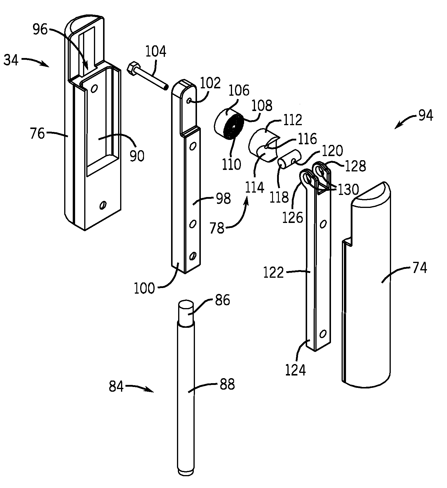
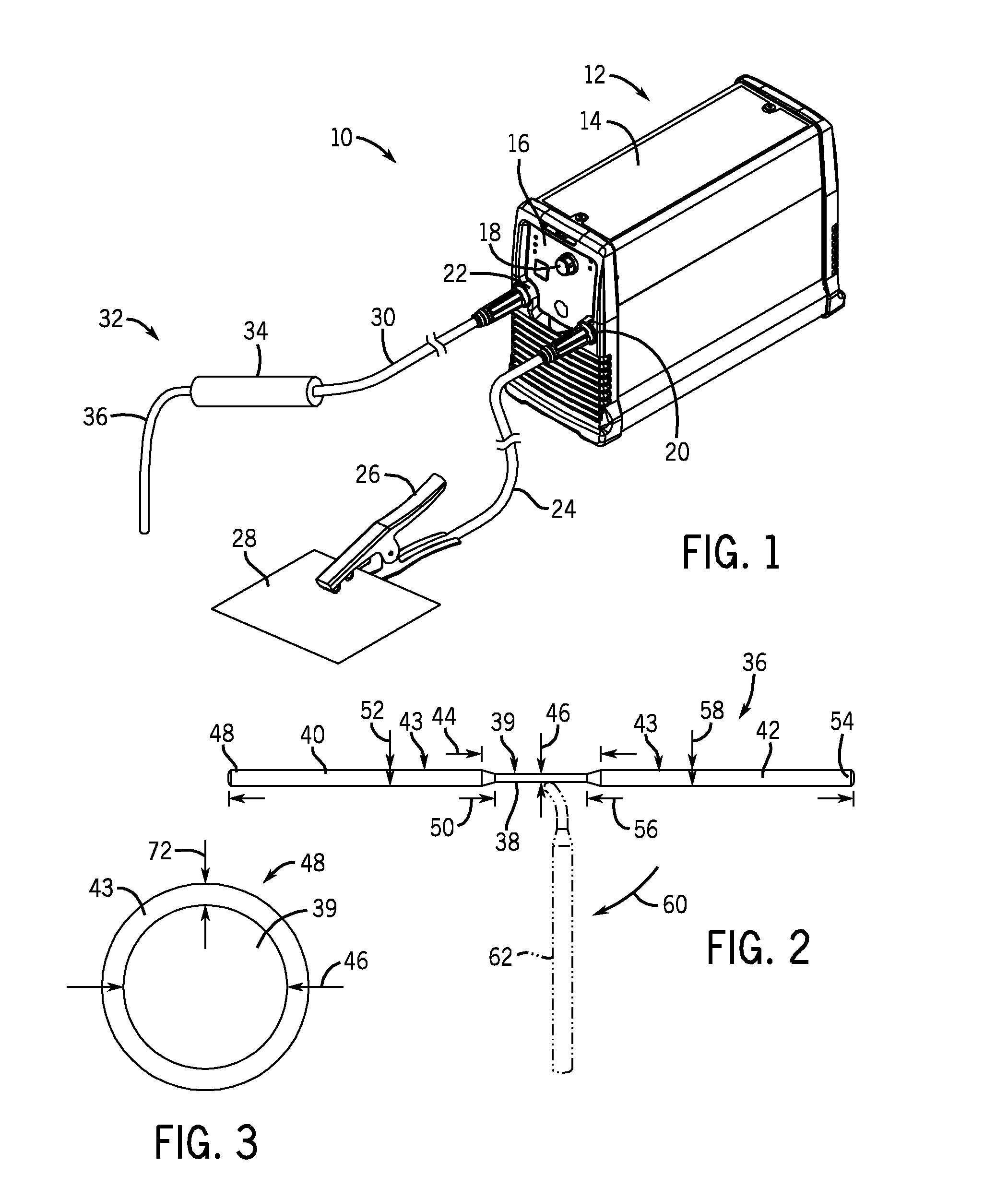
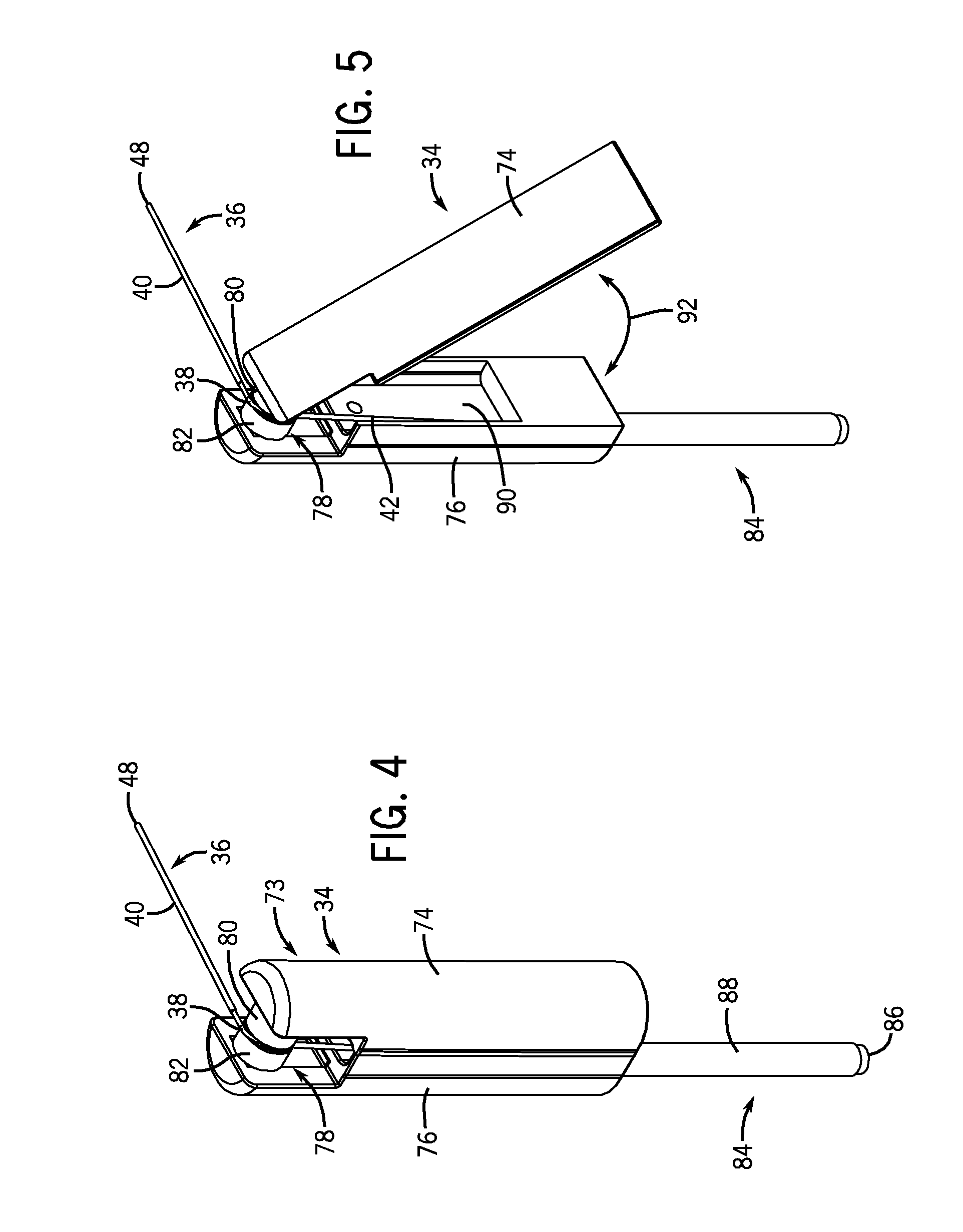
[0020]As described below, provided herein are welding systems including one or more features that may improve the efficiency of a shielded metal arc welding (SMAW) process (i.e., stick welding). For example, embodiments of presently disclosed welding torch assemblies and welding rods may enable a welding operator to more fully utilize the length of a welding electrode in a stick welding process. For example, in one embodiment, a welding electrode is made of an electrode core material having a first flux section and a second flux section that flank an exposed central section. The foregoing embodiment of the welding electrode may be compatible with embodiments of welding electrode holders disclosed herein to provide for arc ignition and welding with both the first flux section and the second flux section, one at a time. To that end, welding electrode holders disclosed herein may include securing assemblies and insulating assemblies capable of securing the central section of the weldin...


PUM

PropertyMeasurementUnit
distanceaaaaaaaaaa
distanceaaaaaaaaaa
distanceaaaaaaaaaa

Abstract

A welding torch with a welding electrode and a welding electrode holder is provided. One welding torch includes a securing mechanism and an insulated grip. The securing mechanism is configured to secure an exposed central portion of a welding rod bounded by flux covered first and second sides. The securing mechanism is also configured to make electrical contact with the central portion of the rod for arc welding with the first side. The insulated grip is configured to cover the second side of the welding rod.

Description

CROSS-REFERENCE TO RELATED APPLICATIONS[0001]This application is a Non-Provisional Patent Application of U.S. Provisional Patent Application No. 61 / 346,970 entitled “Welding Electrode Holder with Specialized Electrode”, filed May 21, 2010, which is herein incorporated by reference.BACKGROUND[0002]The invention relates generally to a welding torch and, more particularly, to a welding electrode and a welding electrode holder.[0003]Welding is a process that has become increasingly ubiquitous in various industries and applications. While such processes may be automated in certain contexts, a large number of applications continue to exist for manual welding operations. Such welding operations rely on a variety of types of equipment to ensure the supply of welding consumables (e.g., electrodes, etc.) is provided to the weld in an appropriate amount at the desired time. For example, shielded metal arc welding (SMAW) typically relies on a welding electrode to provide filler material for a w...

Claims


Application Information

Patent Timeline
Patent Type & Authority Patents(United States)
IPC IPC(8): B23K9/00B23K9/10B23K9/28B23K35/02B23K35/40
CPCB23K35/404B23K9/0008B23K9/282B23K35/0261
Inventor RAPPL, JAMES FRANCISLAHTI, THOMAS DON
Owner ILLINOIS TOOL WORKS INC
Why Eureka
Try Eureka