Umbrella folding upward and inside out

a folding umbrella and umbrella frame technology, applied in umbrellas, walking sticks, clothing, etc., can solve the problems of limiting the capacity of the umbrella frame, difficult to incorporate the cover and the lid as a single unit, and difficult to store in a cover pouch, so as to reduce the visual impact of the handle, the effect of inherent stiffness

Active Publication Date: 2014-11-25
KAZIM JENAN
View PDF18 Cites 7 Cited by
  • Summary
  • Abstract
  • Description
  • Claims
  • Application Information

AI Technical Summary

Benefits of technology

[0030]Preferably the motion of the outer strut is actuated by means of a push pull rod which connects via a lever arm to the outer strut wherein pushing or pulling the push pull rod results in the outer strut pivoting the hinge assembly. Preferably the hinge assembly further comprises a spring rod the spring rod being adapted to resist movement of the outer strut about the hinge assembly without the movement being replicated by the push pull rod. This results in a wind resistant outer strut which will always return to its open rest position after being blown in the wind, but which will easily fold away when desired.
[0044]It is recognised by the inventor that the existing umbrellas, even with the weaknesses outlined above are commercial reality and as such they have public acceptance. This innovation maintains the visual and operational characteristics of the existing umbrellas but with added advantage of being dry to handling, non drip, wind resistant and inherently safer to fold.

Problems solved by technology

There are a number of disadvantages of the conventionally designed compact umbrellas as listed below:
The folding process requires handling of the wet fabric and even when fully folded it does not prevent water dripping from it.
A separate pouch is required to store the folded umbrella and as much of the fabric is loose and wet, it is difficult to store in a cover pouch.
It is also difficult to incorporate the cover and the lid as part of a single unit.
The arrangement of the spokes, fabric and the folding process limits capacity of the umbrella frame to resist turning inside out against wind.
Various attempts have been made to improve on the conventional umbrella design but, for various reasons, none have yet met with any significant commercial success.
Once again, this is not of the collapsible type and, from the geometry of the struts and ribs, it is doubtful if this could ever be erected.

Method used


Image

  • Umbrella folding upward and inside out
  • Umbrella folding upward and inside out
  • Umbrella folding upward and inside out

Examples


first embodiment

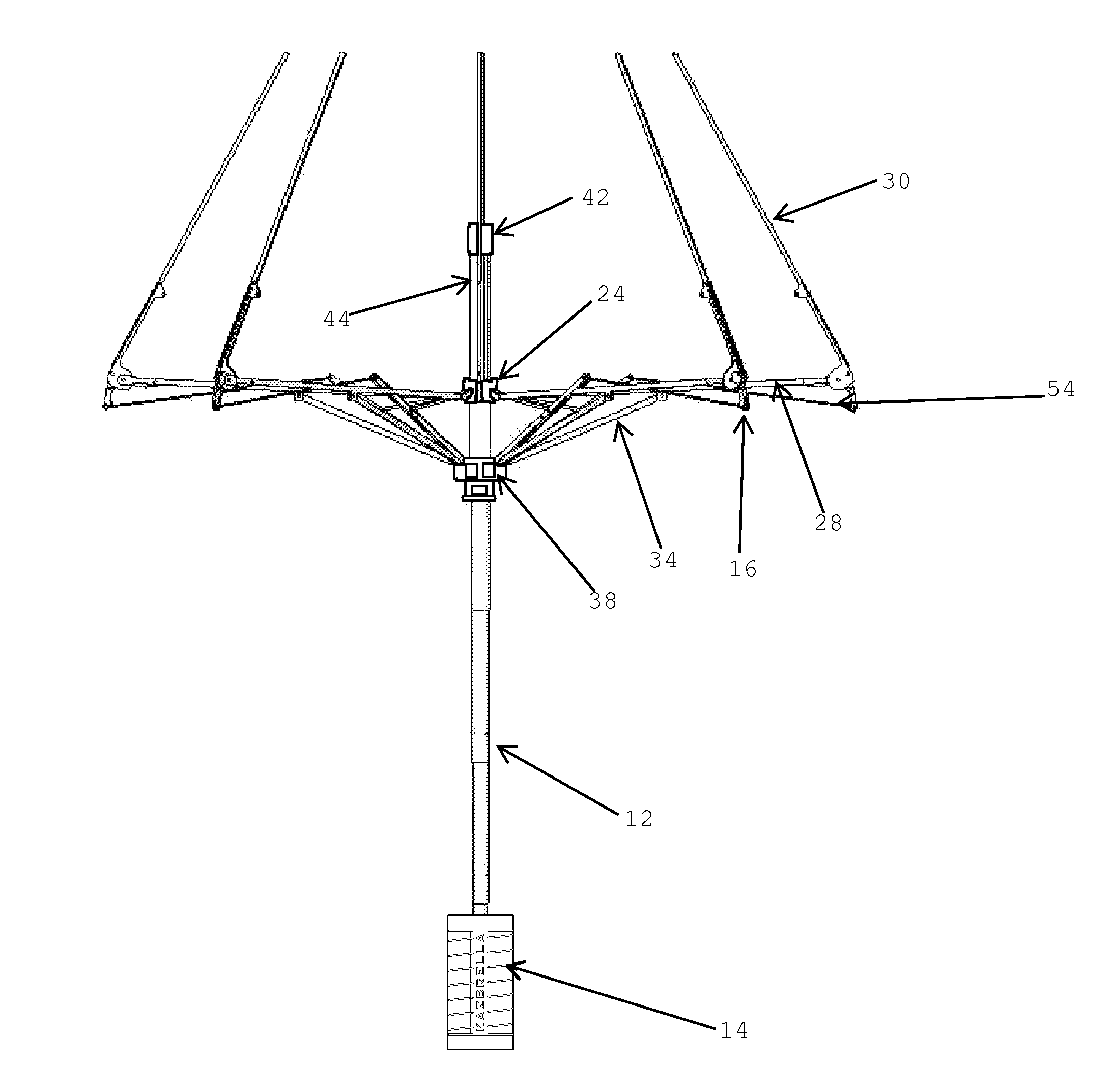
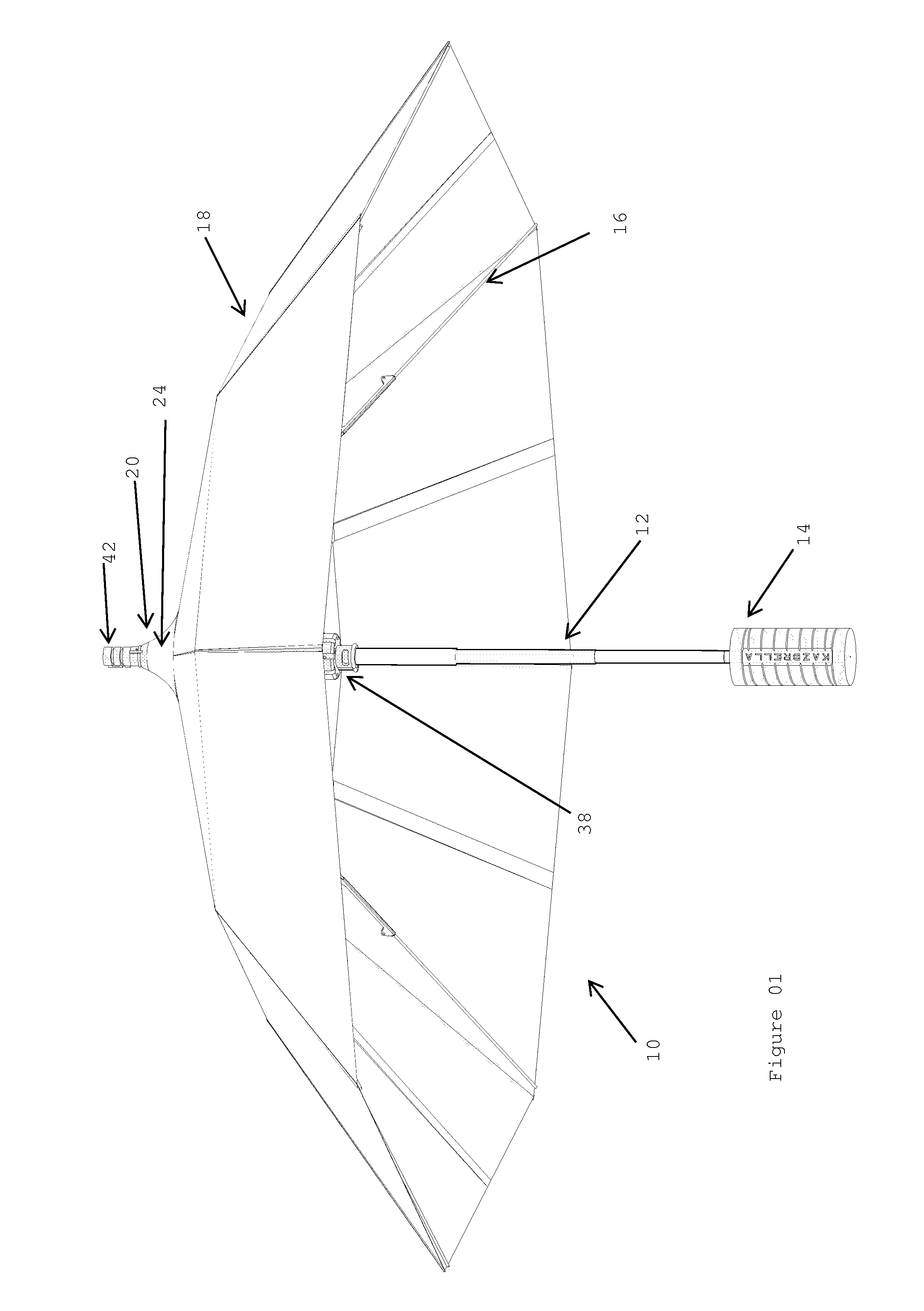
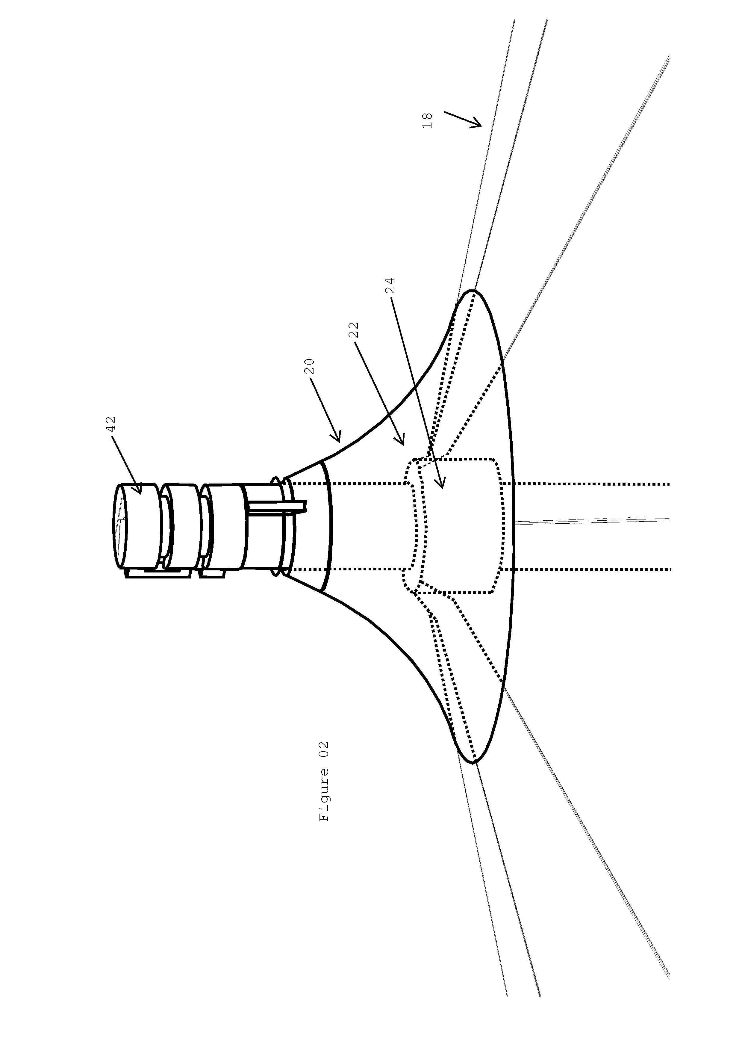
[0072]Referring to FIG. 1 this illustrates an umbrella 10 according to the present invention in its open position. The umbrella 10 has a central spine 12 a handle grip 14, a collapsible canopy framework 16, a main canopy 18 and a mini canopy 20. The main canopy 18 and the mini canopy 20 are both shown as being semi transparent so that the supporting collapsible canopy framework 16 is visible.

[0073]The central spine 12 is telescopic, typically tubular structure that supports the collapsible canopy framework 16 and the main canopy 18. In its lowest section, it supports a handle grip 14. In its uppermost section it supports a pulley system holder which will be described later.

[0074]The handle grip 14 is fixed on to the lowest segment of the central spine 12. This is also usually cylindrical and usually made out of plastic or wood. The optional sleeve cover (not shown) for the umbrella 10 can be fixed onto the handle grip 14.

[0075]The collapsible canopy framework 16 comprises a pluralit...

second embodiment

[0096]FIG. 13 illustrates an umbrella 110 according to the present invention in the open position with the sleeve 182 present and retracted to its open position. The sleeve 182 can be made out of flexible material such as fabric which can roll up or down, or it can be made out of tubing, preferably telescopic with one or more segments and preferably see through to minimise its visual impact. Uniquely, the lid 184 to the sleeve 182 is incorporated onto it. The closing action of the sleeve 182 closes the lid 184 and the opening action of the sleeve 182 opens the lid 184. The advantage of this is that the whole system, including the umbrella 110 and the lid 184 are part of the same unit. Alternatively, the lid 184 of the sleeve 182 can be a separate preferably cylindrical cap to cover the part of the umbrella 110 on the opposite end to the handle 114 or fabric fold and Velcro to fix it. This arrangement has the advantage that the umbrella 110 folds up inside out as well as folding comp...

third embodiment

[0103]Referring to FIG. 19 this illustrates an arm 226 of the collapsible canopy framework 216 of the umbrella 210 according to the present invention. In this case, inner strut 228 is shown on top and the brace 234 at the bottom. The upper crown 224 is shown in two sections, upper section 223 supports the connecting member 256 which connects to the actuation system 256 and the lower section 225 supports the inner strut 228. The brace 234 is supported by the lower crown 238 which also supports the connecting member 256 of the secondary linkage. The connector 277 which connects the two sections 223, 235 of the upper crown 234 allows the upper section 223 to move independently of the lower section 225 up to a certain height and couple them thereafter. On the way down the upper section 223 is free to move until in contact with the lower section 225. In an alternative this can also be achieved using strings or fabric joining the upper section 223 and the lower section 235 of the upper cr...


PUM


Abstract

A foldaway umbrella (10, 110, 210, 310, 410, 510) moveable between an open configuration and a closed configuration, said umbrella comprising: k) a central spine (12, 112, 212, 312, 312, 412, 512); l) an upper crown (24, 124, 224, 324, 424, 524) moveable with respect to the central spine; m) a lower crown (38, 138, 238, 338, 438, 538) fixed with respect to the central spine; n) a collapsible canopy framework (16, 116, 216, 316, 416, 516) connected to the upper crown and the lower crown; and o) a main canopy (18, 118, 218, 318, 418, 518) covering the collapsible canopy framework said main canopy (18, 118, 218, 318, 418, 518) covering the collapsible canopy framework said main canopy having an inside face closest to the collapsible canopy framework and an outside face crown from a position remote of the lower crown to a position close to the lower crown results in the collapsible canopy framework, and thus the main canopy, to move from the open configuration to the closed configuration wherein the main canopy is folded inside out such that only the inside face of the main canopy is exposed and vice versa.

Description

FIELD OF THE INVENTION[0001]The present invention relates to folding umbrellas. It is particularly applicable to folding umbrellas in which the umbrella canopy folds away inside out.BACKGROUND[0002]There have been many years of development in designing compact umbrellas, typically following the same principle of utilising a taut wire to stiffen the spokes that support the canopy. The spokes are normally in 3 or 4 hinged segments, which are foldable, with the canopy fabric being gathered around them. Normally a pouch is also provided for storing the folded umbrella. There are a number of disadvantages of the conventionally designed compact umbrellas as listed below:[0003]The supporting spokes are folded such that the canopy fabric is gathered around them and a substantial part of the wet side of the fabric is on the outside.[0004]The folding process requires handling of the wet fabric and even when fully folded it does not prevent water dripping from it.[0005]A separate pouch is requ...

Claims


Application Information

Patent Timeline
Patent Type & Authority Patents(United States)
IPC IPC(8): A45B25/10A45B25/24A45B25/14A45B19/04A45B19/00A45B19/10
CPCA45B19/10A45B2019/008A45B19/04A45B25/24A45B25/14A45B25/10A45B2025/105
Inventor KAZIM, JENAN
Owner KAZIM JENAN
Why Eureka
Try Eureka