
External beam delivery system using catadioptric objective with aspheric surfaces

a catadioptric and objective technology, applied in the field of optical imaging, can solve the problems of compromising sensitivity, unable to meet the requirements of advanced specimen inspection, and unable to meet the requirements of advanced specimen inspection, and achieve the effect of facilitating dark-field inspection of specimens

Active Publication Date: 2014-11-25
KLA CORP
View PDF10 Cites 13 Cited by
  • Summary
  • Abstract
  • Description
  • Claims
  • Application Information

AI Technical Summary

Benefits of technology

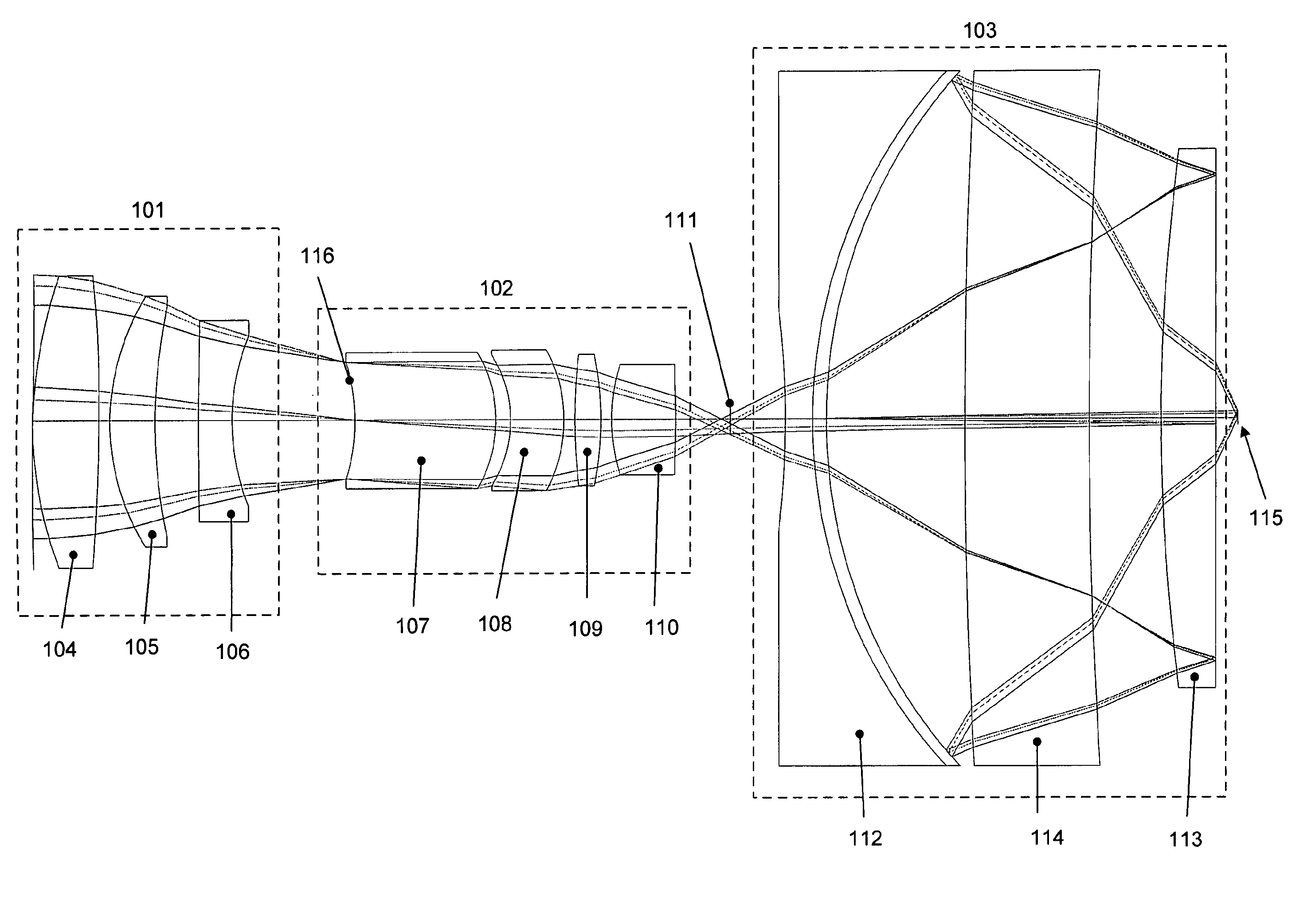
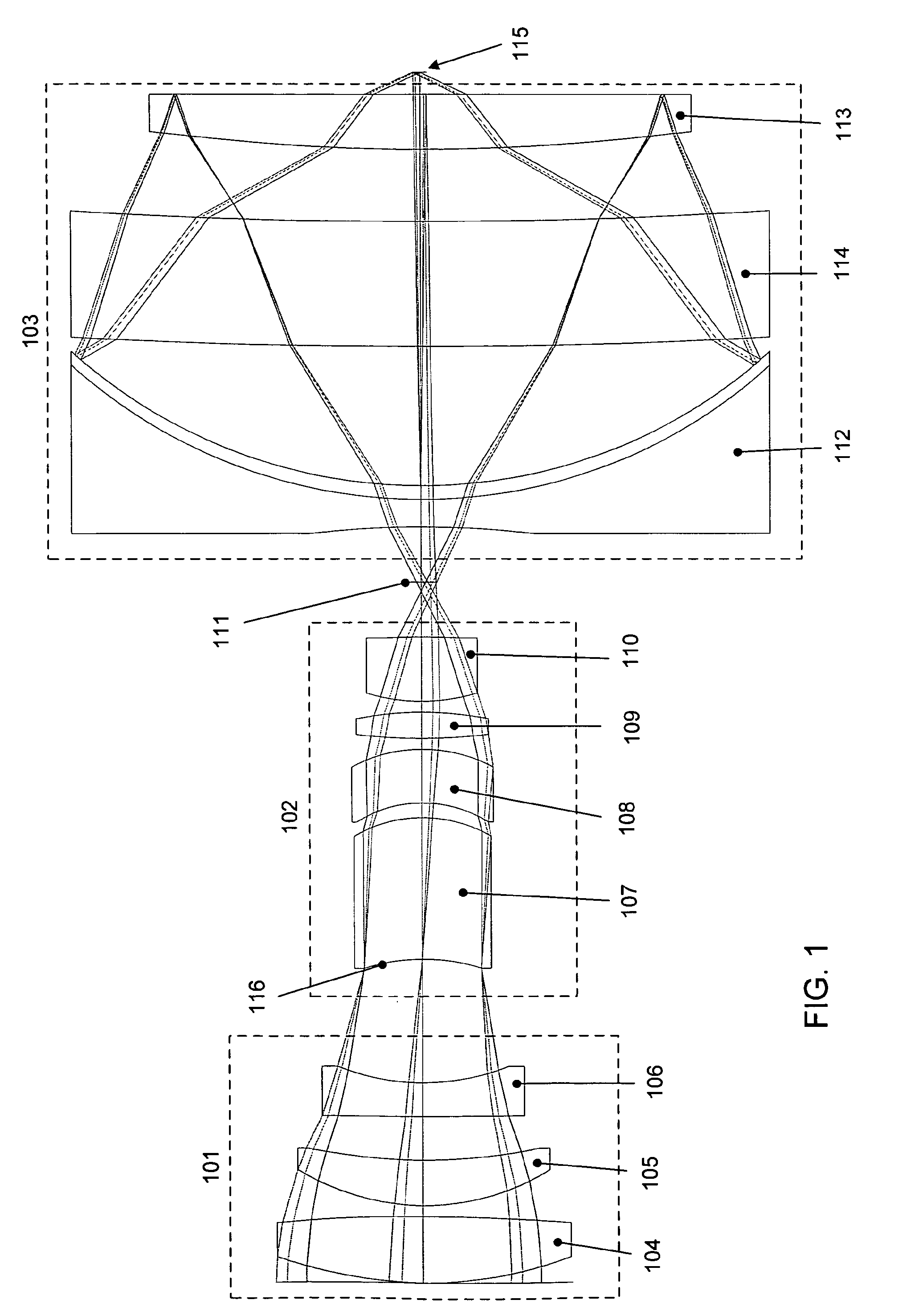
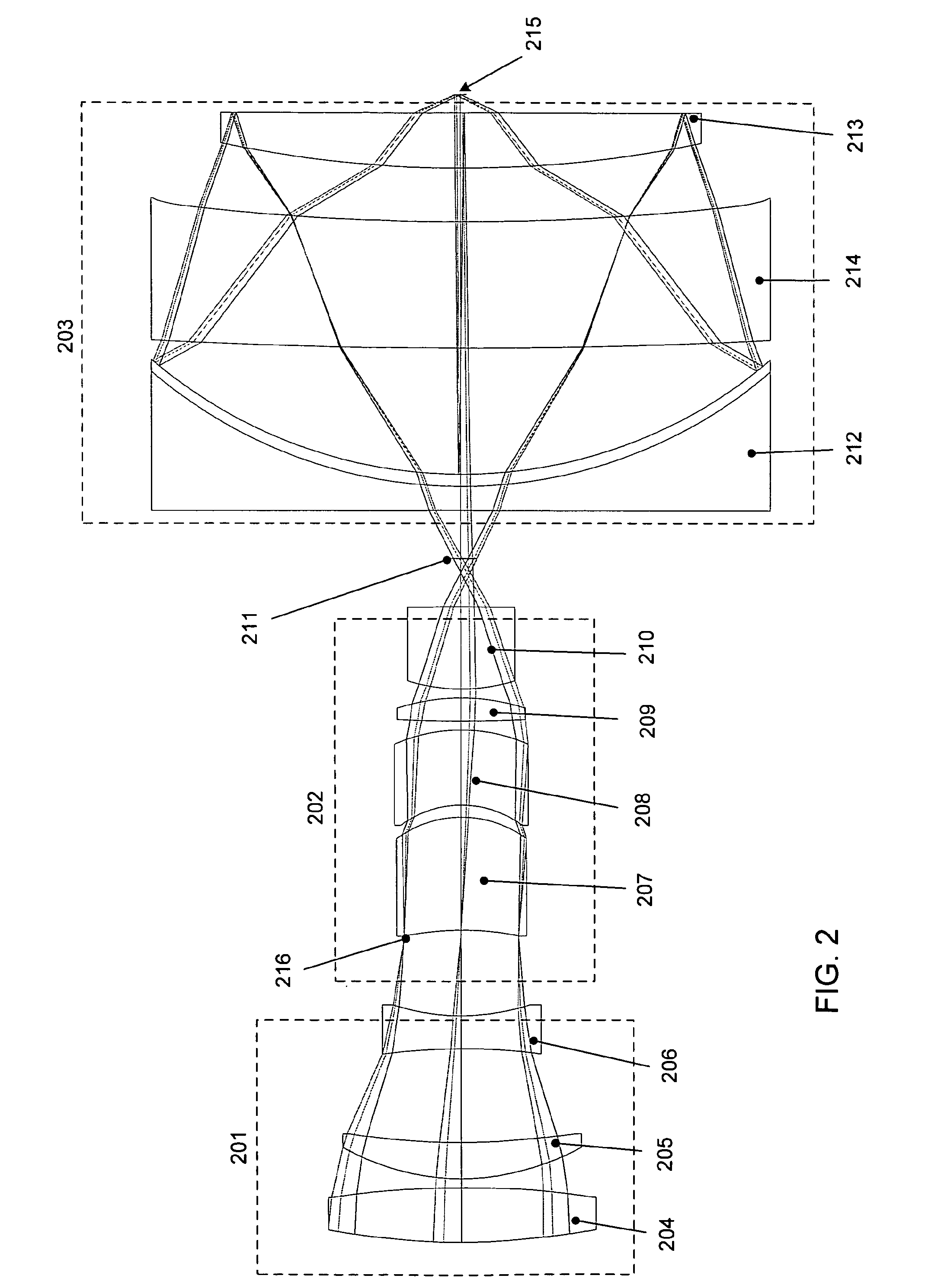
[0012]According to one aspect of the present design, a catadioptric objective is provided. The catadioptric objective includes an outer element furthest from the specimen and comprising an outer element partial reflective surface oriented toward the specimen, an inner element nearest the specimen comprising an inner element partial reflective surface oriented away from the specimen, and a central element positioned between the outer lens and the inner lens. At least one of the outer element, inner element, and central element comprises an aspheric surface. The inner element is spatially configured to facilitate dark-field inspection of the specimen.

Problems solved by technology

When combined with the beam delivery and low scattering requirements of oblique dark-field imaging, finding a suitable design for advanced specimen inspection becomes very challenging.
These previous designs can, in certain circumstances, exhibit beam delivery issues when performing oblique dark-field imaging.
However, small amounts of scattered and reflected light from lens elements using this design can produce optical noise at levels that compromise sensitivity.
These methods of illumination can cause a significant amount of back-scattered and reflected light from the multiple lens surfaces traversed by the illuminating light.
Forward-scattered light from the specularly reflected component off the wafer can also be a significant potential problem.
A major drawback of this approach is the small imaging NA that limits the amount of scattered light that can be collected.
Another drawback is the small spectral bandwidth and small field size that are typical of refractive UV-DUV objectives.
Such objectives exclusively employ spherical optical surfaces and have certain issues when implemented.

Method used


Image

  • External beam delivery system using catadioptric objective with aspheric surfaces
  • External beam delivery system using catadioptric objective with aspheric surfaces
  • External beam delivery system using catadioptric objective with aspheric surfaces

Examples


Embodiment Construction

[0024]A catadioptric objective configured to inspect a specimen is provided. The objective includes a plurality of lenses, an element with an aspheric surface shape, and the design supports a bandwidth of at least 0.25 nm. The objective may be successfully employed in oblique laser dark-field mode inspection of specimens, such as semiconductor wafers.

[0025]Oblique laser dark-field inspection relies on detecting light scattered from a defect on a specimen, such as a semiconductor wafer. Inspection systems employing oblique laser dark-field mode can detect defects sized below the resolution of the optical system. Flat areas on the specimen that scatter minimal light toward the detector produce a dark image. Any surface anomalies or features protruding above the object tend to scatter light toward the detector, and when inspecting objects such as semiconductor wafers, dark-field imaging yields bright areas representing features, particles, or other irregularities on a dark background.

[...


PUM


Abstract

An inspection system including a catadioptric objective that facilitates dark-field inspection is provided. The objective includes an outer element furthest from the specimen having an outer element partial reflective surface oriented toward the specimen, an inner element nearest the specimen having a center lens comprising an inner element partial reflective surface oriented away from the specimen, and a central element positioned between the outer lens and the inner lens. At least one of the outer element, inner element, and central element has an aspheric surface. The inner element is spatially configured to facilitate dark-field inspection of the specimen.

Description

[0001]This application claims the benefit of U.S. Provisional Patent Application 61 / 132,438, entitled “External Beam Delivery System Using Catadioptric Objective with Aspheric Surfaces,” inventor J. Joseph Armstrong, filed Jun. 17, 2008, which is incorporated herein by reference.BACKGROUND OF THE INVENTION[0002]1. Field of the Invention[0003]The present invention relates generally to the field of optical imaging, and more specifically to catadioptric optical systems used for bright-field and dark-field optical inspection applications.[0004]2. Description of the Related Art[0005]Many optical and electronic systems inspect surface features for defects such as those on a partially fabricated integrated circuit or a reticle. Defects may take the form of particles randomly localized on the surface, scratches, process variations such as under etching, and so forth. Such inspection techniques and devices are well known in the art and are embodied in various commercial products such as many...

Claims


Application Information

Patent Timeline
Patent Type & Authority Patents(United States)
IPC IPC(8): G02B21/12G02B17/08G02B21/04G02B21/10G02B21/00
CPCG02B17/0808G02B21/125G03F7/70225G02B21/04G02B21/0016G02B17/0856
Inventor ARMSTRONG, J., JOSEPH
Owner KLA CORP
Learn More