Multi-layer curved surface compound eye type 180° large field of view imaging system

An imaging system and curved surface compound eye technology, which is applied to optical components, optics, instruments, etc., can solve the problems of less design freedom, low imaging quality, and difficult processing, and achieve a compact overall structure, easy application, and good imaging quality. Effect

Active Publication Date: 2016-01-20
MDTP OPTICS
View PDF5 Cites 2 Cited by
  • Summary
  • Abstract
  • Description
  • Claims
  • Application Information

AI Technical Summary

Problems solved by technology

The field of view of this type of compound eye is higher than that of the planar structure, but in order to adapt to the commonly used CCD size, the size of this type of compound eye device is small, so that the light flux of each sub-eye channel is low, and it is only sensitive to high-brightness objects or close-range targets. , and the image quality is poor, similar to real compound eyes of insects
Analyzing the reasons, there are mainly two aspects: on the one hand, because the curved compound eye at the present stage is only a lens array composed of single lenses, according to the aberration theory, it can be known that the design freedom of this structure is less, and it is difficult to correct the effects that affect the imaging quality. Various aberrations, so the imaging range of each microlens is limited, and the imaging quality is not high. In order to obtain a larger field of view, it is necessary to distribute more sub-eye microlenses on the curved surface substrate, which gives the Processing poses great difficulties
On the other hand, since the image sensors at this stage are all planar structures, this structure makes the optical axis of each microlens have an angle with it, and this angle inevitably brings defocus to the image points in the peripheral field of view of the microlens. , which is unacceptable for imaging systems
[0005] To sum up, due to the constraints of current processing technology, imaging quality and other factors, a compound eye system with a field of view of 180°, a compact overall structure, and high image quality has not yet been realized.

Method used


Image

  • Multi-layer curved surface compound eye type 180° large field of view imaging system
  • Multi-layer curved surface compound eye type 180° large field of view imaging system
  • Multi-layer curved surface compound eye type 180° large field of view imaging system

Examples


Embodiment Construction

[0029] The present invention will be further illustrated below in conjunction with the accompanying drawings and specific embodiments. This embodiment is implemented on the premise of the technical solution of the present invention. It should be understood that these embodiments are only used to illustrate the present invention and are not intended to limit the scope of the present invention.

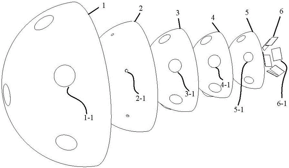
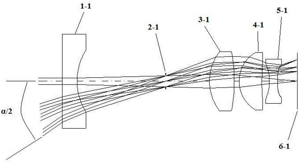
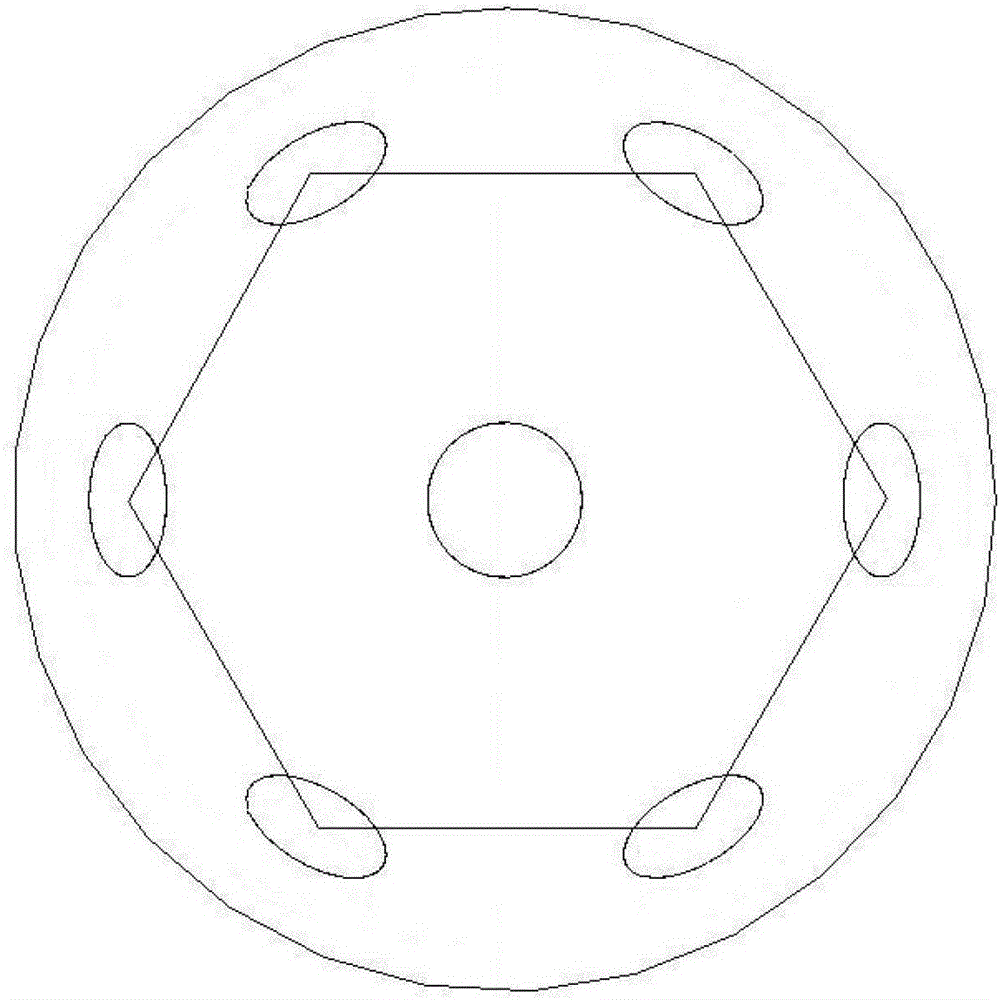
[0030] figure 1The multilayer curved fly-eye lens described in this embodiment includes a first layer of lens array 1, an aperture array 2, a second layer of lens array 3, a third layer of lens array 4, and a fourth layer of lens array 5 arranged in sequence. And the image sensor array 6; each layer of lens array is on a spherical substrate, with the spherical apex as the center, a microlens is placed as the central lens, and its optical axis passes through the spherical apex and the center of the sphere, and outside it is a hexagonal Six microlenses are arranged in the structure, and ...


PUM


Abstract

The invention discloses a multilayer curve compound eye type imaging system with a large visual field of 180 DEG. The system comprises a first layer of lens array, a second layer of lens array, a third layer of lens array, a fourth layer of lens array and an image sensor array arranged in sequence; all layers of lens arrays are arranged on the same spherical substrate, a spherical peak is used as a center, a micro lens is placed as a central lens, the optical axis of the micro lens passes through the spherical peak and a spherical center, six micro lenses are arranged outside the micro lens by using hexagonal structures, and the included angles between the optical axes of the six micro lenses and the optical axis of the central lens are all equal to theta; and all the lens arrays and the image sensor array are arranged in the same way. The design concept of a multilayer compound eye structure is adopted, and incident light from different visual fields is received in a way of multi-path CCD (Charge Coupled Detector) combination, so that the lens can obtain an image with higher quality while ensuring the characteristics of compound eye and large visual field; and in addition, the multilayer curve compound eye type imaging system is small and compact in whole structure and convenient to apply.

Description

technical field [0001] The invention relates to the field of bionic compound eye imaging, in particular to a large field of view imaging system. Background technique [0002] In recent years, the bionic compound eye imaging system has attracted extensive attention of researchers. Its unique characteristics of large field of view, small size, and high sensitivity to moving objects make it have great potential for applications in medical, industrial, and national defense fields. . The compound eye is a small and precise optical structure existing in nature. Different from the single-aperture imaging system we are familiar with, the compound eye is composed of many hexagonal sub-eye units, and these hexagonal sub-eyes are closely arranged on a curved surface. Each sub-eye is composed of corneal lens, cone, rods and photoreceptor cells. Due to the small size, each sub-eye can only image a certain field of view in the space. When all the sub-eyes work together, they can detect...

Claims


Application Information

Patent Timeline
Patent Type & Authority Patents(China)
IPC IPC(8): G02B27/00G02B13/18G02B13/00
Inventor 房丰洲宋乐张红霞邹成刚范阳
Owner MDTP OPTICS
Why Eureka
Try Eureka