Projection light module for a motor vehicle headlamp having a central lens mount

a technology of projection light and motor vehicles, which is applied in vehicle lighting systems, lighting and heating apparatus, and light fastenings to achieve the effects of simple installation, high precision and simplified installation of projection light modules

Inactive Publication Date: 2016-02-18
AUTOMOTIVE LIGHTING REUTLINGEN GMBH
View PDF5 Cites 2 Cited by
  • Summary
  • Abstract
  • Description
  • Claims
  • Application Information

AI Technical Summary

Benefits of technology

[0012]Because the position of the mirrored shutter in relation to the two components of the lens mount is determined by inter-engaging form-fitting elements, a very simple installation of the mirrored shutter is obtained, in conjunction with a very high precision for the position of the shutter edge in relation to the lens mount. The clamping attachment likewise contributes, in conjunction with the form-fitting positioning, to a very low installation effort. Because the mirrored shutter has spacers facing toward the projection lens, which are in contact with the projection lens, a very high precision for the determination of the spacing between the shutter edge and the light entry surface of the projection lens is obtained, in conjunction with a very low installation effort.
[0013]As a result, the intensity of a color fringe is then dominated by the component manufacturing tolerances. The installation tolerances are negligible in comparison. It is then no longer necessary to adjust the color fringe when the remaining imprecision of the specified spacing is no greater than ±0.2 mm, which can be obtained with a typical manufacturing precision of the parts.
[0014]The possible elimination of the color fringe adjustment for low beam light, without sacrificing quality, reduces the manufacturing effort and the manufacturing costs, which is a substantial development objective. The fact that, with standard lens edge geometries, an attachment of the lens without additional parts can occur, likewise contributes to lower costs. Furthermore, the invention makes it possible to eliminate a heat sink, or at least to use a smaller heat sink than that used in the prior art. On the whole, a simplified production is obtained, in conjunction with lower tolerances and a reduction in the structural space, weight and costs. The object of the invention can thus be seen as that of providing a projection light module having these advantages, and which can be, in particular, manufactured in a very inexpensive manner, having acceptable lighting properties.

Problems solved by technology

If no color fringe adjustment of this type is carried out, the color of the light at the light / dark border, depending on the magnitude of the tolerances, would constantly fluctuate on the street, which is distracting.

Method used


Image

  • Projection light module for a motor vehicle headlamp having a central lens mount
  • Projection light module for a motor vehicle headlamp having a central lens mount
  • Projection light module for a motor vehicle headlamp having a central lens mount

Examples


Embodiment Construction

[0033]Identical reference symbols indicate identical elements in the various figures thereby, or at least elements having comparable functions.

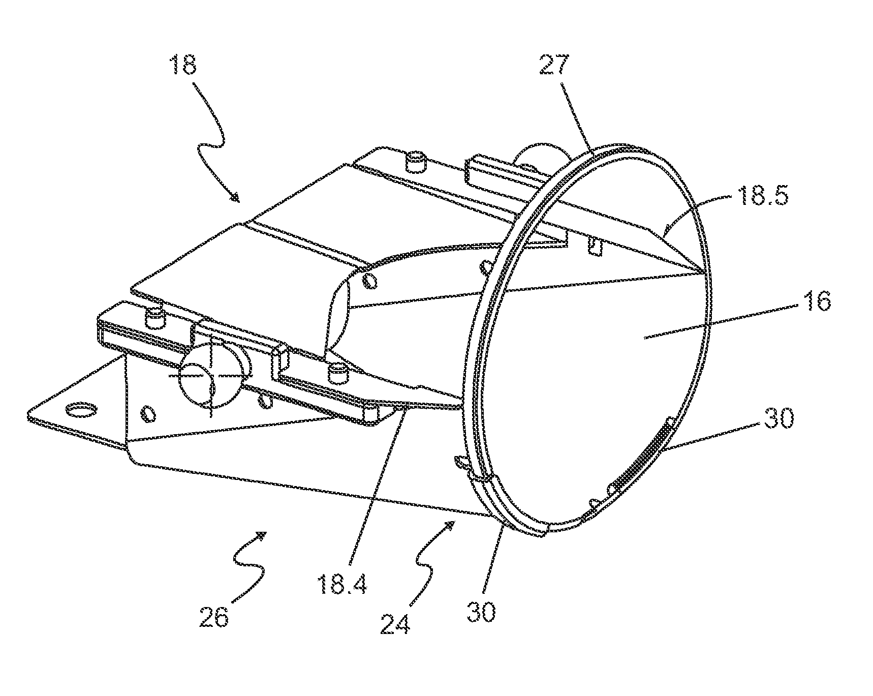
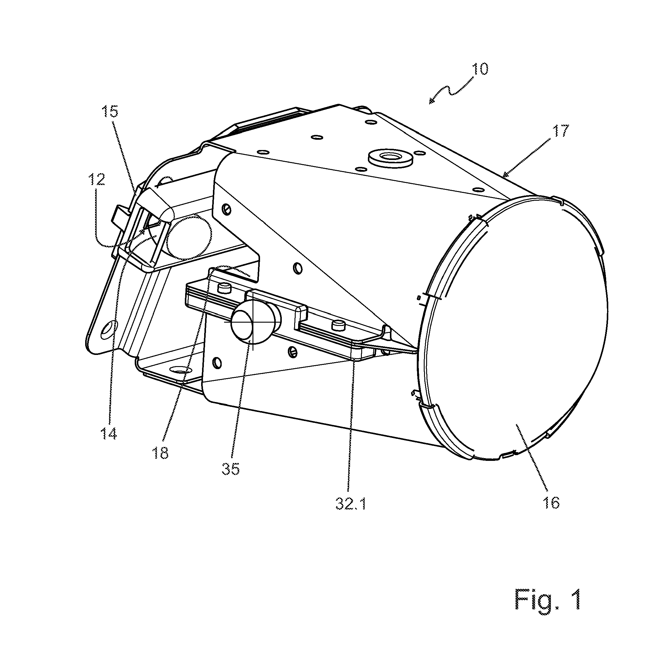
[0034]FIG. 1 shows one exemplary embodiment of a projection light module 10 according to the invention in detail, for a motor vehicle headlamp having a light source 12, a primary lens 14 and a projection lens 16. Furthermore, the projection light module 10 has a mirrored shutter 18, which can be seen more clearly in other figures. The projection light module 10 has a first retaining structure 17, which retains the light source 12, the primary lens 14, the mirrored shutter 18 and the projection lens 16.

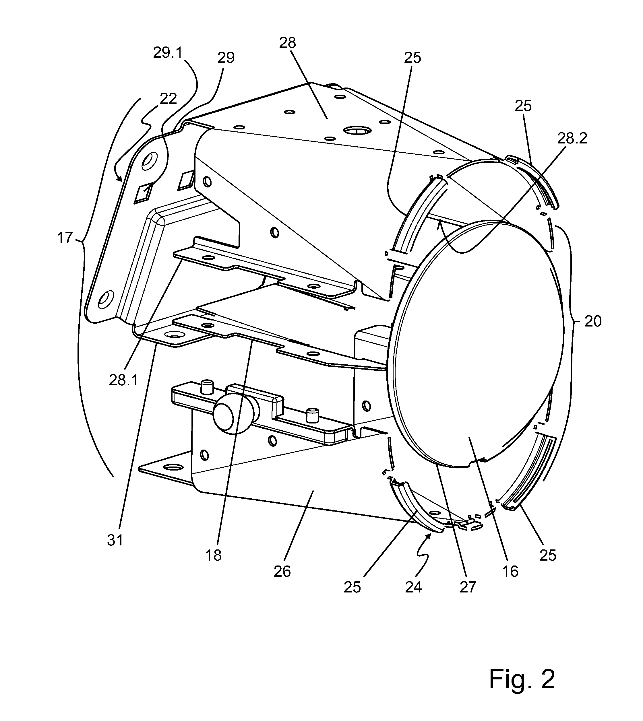
[0035]FIG. 2 shows the projection light module 10 from FIG. 1 in an exploded view. The first retaining structure 17, which retains the light source, the primary lens, the mirrored shutter 18 and the projection lens 16, has, in particular, a lens mount 20, having a light source side end 22 and a projection lens side end 24. The projection lens si...


PUM


Abstract

A projection light module for a motor vehicle headlamp having a lens mount that is divided into a first component and a second component, wherein a separating surface lying between the two components cuts the lens receiver, the mirrored shutter is clamped between the first component and the second component, wherein the position of the mirrored shutter in relation to the two components of the lens mount is determined by form fitting element that engage with one another, and the mirrored shutter has spacers facing toward the projection lens, which are in contact with the projection lens.

Description

CROSS-REFERENCE TO RELATED APPLICATIONS[0001]The present application claims priority to and all the benefits of German Patent Application No. 10 2014 216 127.4, filed on Aug. 13, 2014, which is hereby expressly incorporated herein by reference in its entirety.BACKGROUND OF THE INVENTION[0002]1. Field of the Invention[0003]The present invention relates to a projection lens module for a motor vehicle headlamp having a central lens mount.[0004]2. Description of the Related Art[0005]A light module of this type is generally known in the related art and has a light source, a primary lens that bundles the light from the light source into an intermediate light distribution, a mirrored shutter delimiting the intermediate light distribution with a shutter edge, a projection lens that projects the delimited intermediate light distribution in a region in front of the light module, and a retaining structure that retains the light source with the primary lens, the mirrored shutter and the project...

Claims


Application Information

Patent Timeline
Patent Type & Authority Applications(United States)
IPC IPC(8): F21S8/10F21W107/10
CPCF21S48/1216F21W2101/10F21S48/1317F21V14/02F21V17/14F21S41/295F21S41/32F21S41/39F21S41/43F21S41/47F21W2102/20F21W2102/00
Inventor ROTTSTAEDT, OLAF
Owner AUTOMOTIVE LIGHTING REUTLINGEN GMBH
Why Eureka
Try Eureka