Method and apparatus for obtaining optical center lens, attaching lens to a lens holder, and producing lens

a technology of optical center and lens holder, which is applied in the direction of spectacle/goggles, instruments, manufacturing tools, etc., can solve the problems of not always being able to accurately determine the position of the optical center using this prior art method, and the process is complicated and difficult. achieve the effect of accurately and efficiently measuring the optical center of the spectacle lens and efficiently attaching the lens holder

Inactive Publication Date: 2003-08-19
HOYA CORP
View PDF7 Cites 1 Cited by
  • Summary
  • Abstract
  • Description
  • Claims
  • Application Information

AI Technical Summary

Benefits of technology

The object of the present invention is to provide a method for accurately and efficiently measuring the optical center of a spectacle lens, wherein the method includes a method or steps for attaching a lens holder to a spectacle lens so that the position of the attached len...

Problems solved by technology

Therefore, if an uncut spectacle lens is processed merely with the intent of aligning the geometrical center of the lens frame shape with the position of the optical center of the lens, then a problem arises because the pupil center is not necessarily aligned with the geometrical center of the frame and the optical center of the lens.
However, from a practical standpoint it remains a complicated and difficult process to visually measure the prism value with a lens meter at positions considered to be close to the optical center, and it is even more problematic to find the position having a prism value of zero.
Moreover, it is not always possible to accurately determine the position of the optical center using this prior art method.
The alternate prior art method for obtaining the position of the optical center by measuring the prism value of the lens near, or approximate to, the optical center and then calculating the optical center position in accordance with a specific equation suffers from the fact that the accuracy is different depending on the position of the measurement.
The error in calculating the optical center position ...

Method used


Image

  • Method and apparatus for obtaining optical center lens, attaching lens to a lens holder, and producing lens
  • Method and apparatus for obtaining optical center lens, attaching lens to a lens holder, and producing lens
  • Method and apparatus for obtaining optical center lens, attaching lens to a lens holder, and producing lens

Examples


Embodiment Construction

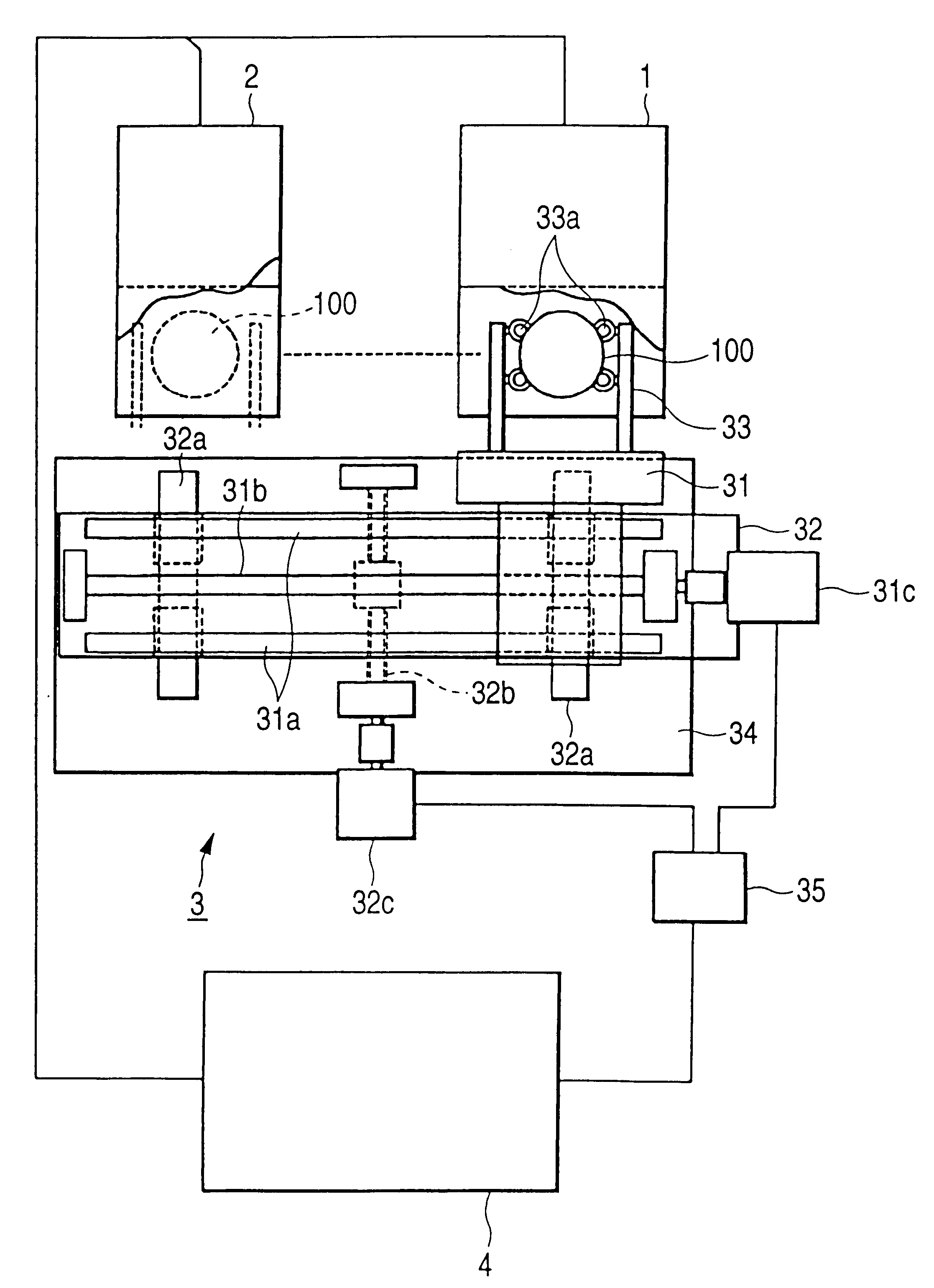
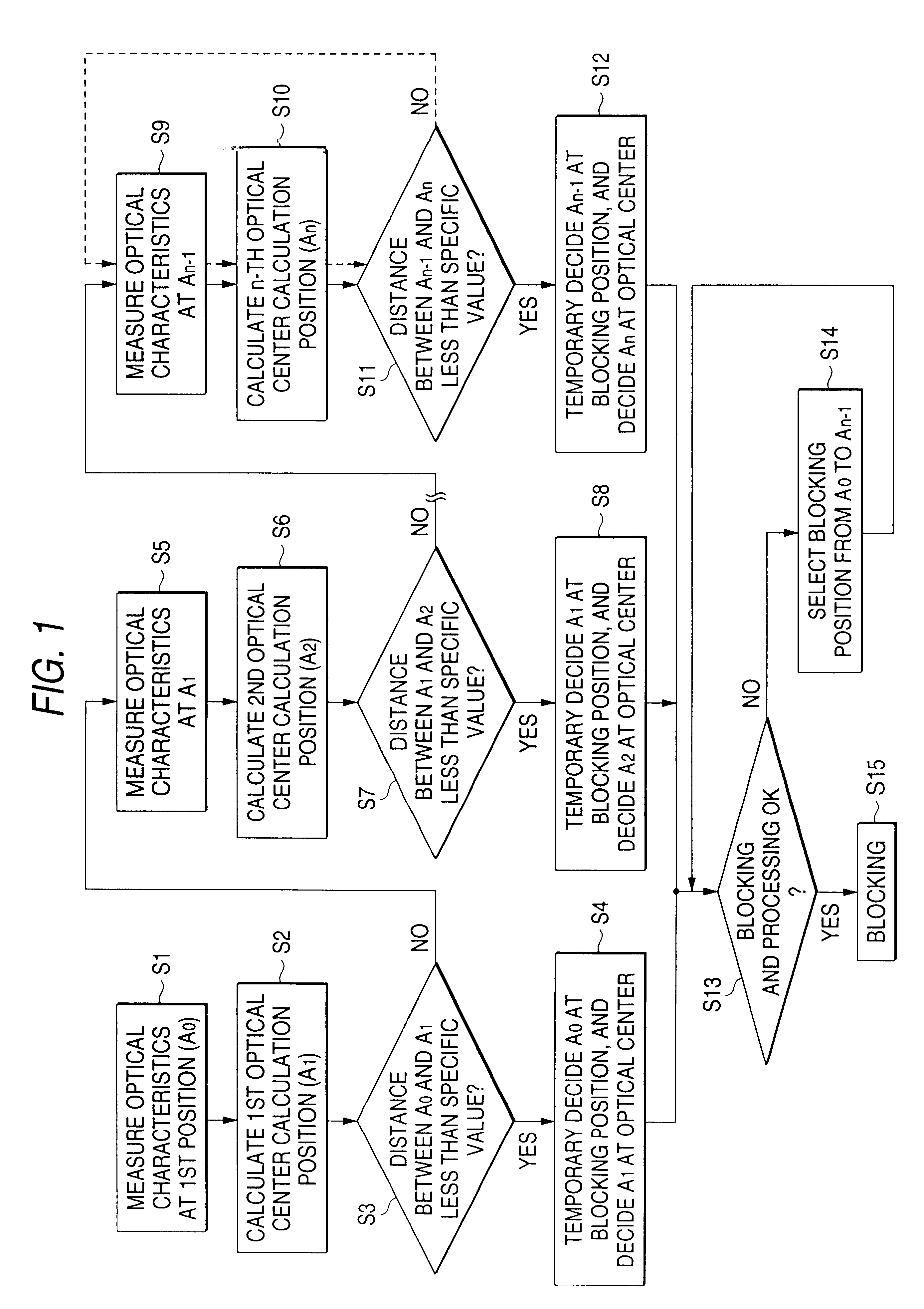
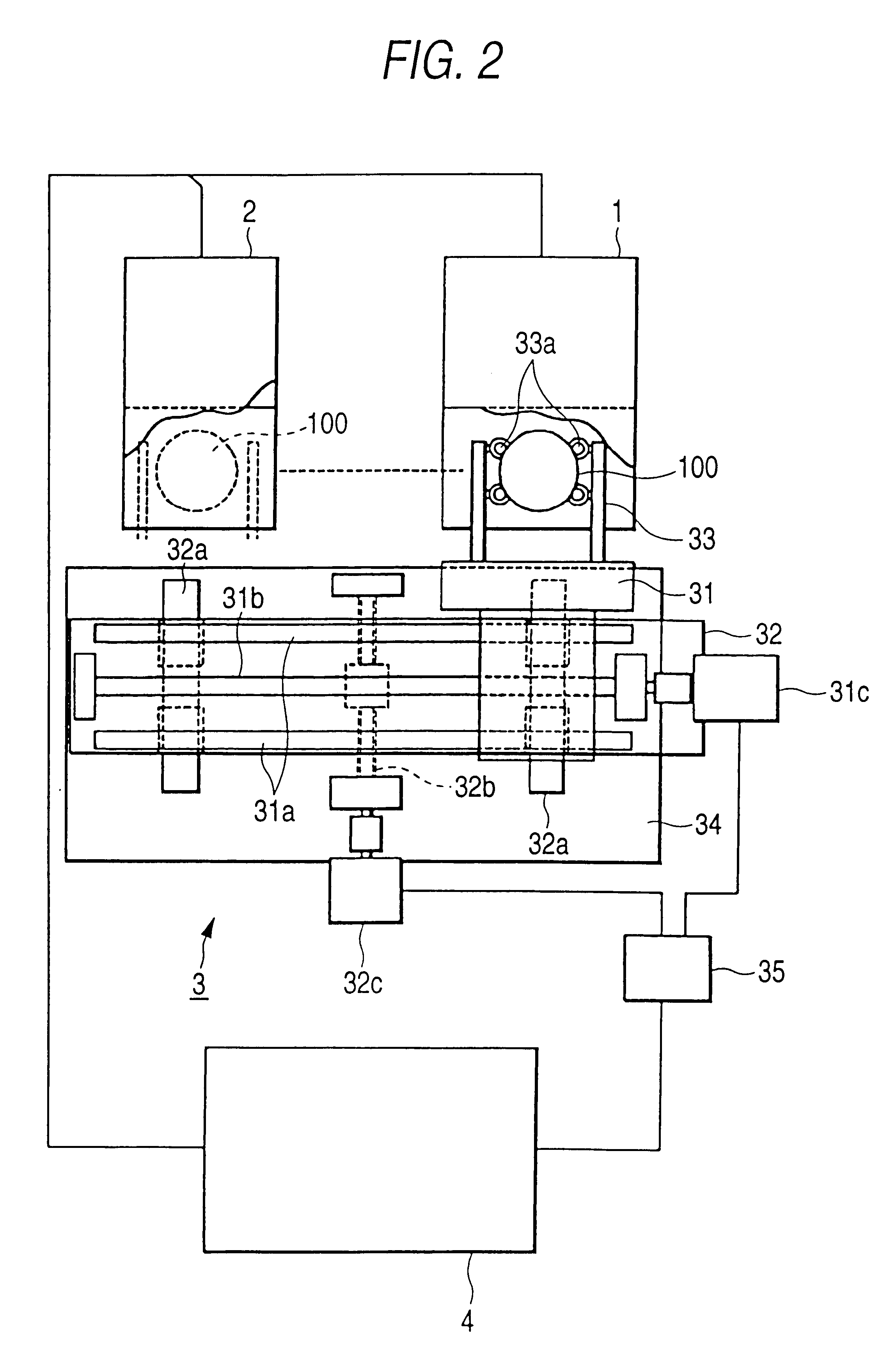
FIG. 1 is a flow chart outlining the steps of the method for determining or obtaining the position of the approximate optical center of a spectacle lens and for attaching a lens holder to the approximate optical center of the spectacle lens. This method for obtaining the position of the optical center of a spectacle lens and for attaching a lens holder to the optical center of the spectacle lens, as well as the apparatus for performing the method of the present invention, will be described with reference to FIGS. 1-5.

Referring to FIG. 1, the method for obtaining the position of the optical center of a spectacle lens and for attaching a lens holder to a spectacle lens comprise steps S1 to S12. These steps essentially achieve the following: (1) setting and measuring the position of an uncut lens on an X-Y table which has movable portions for positioning the uncut lens, (2) taking optical measurements of the uncut lens using a lens meter, and (3) performing a blocking operation by a bl...


PUM


Abstract

The present invention provides a method and apparatus for automatically and continuously conducting the layout analysis, the blocking (attachment) of an uncut lens to a lens holder, and the process of grinding an edge of three types of lenses, such as a single-vision lens, a progressing multifocal lens and a multifocal lens, utilizing a calculated approximation of the optical center of the uncut lens and by determining the position to which a lens holder should attach to the uncut lens.

Description

FIELD OF THE INVENTIONThe present invention relates to a method for obtaining a position of an optical center of a spectacle lens, and a method for attaching a lens holder to an uncut lens. The lens holder is a jig attached in advance to a rotational center axis of the uncut lens prior to a process of grinding an edge of a spectacle lens. The present invention also includes an apparatus for attaching the lens holder to the uncut lens before the process of grinding.BACKGROUND OF THE INVENTIONA spectacle glass, or eyeglass lens, is prepared by processing an uncut spectacle lens (in general, a so-called round lens having a circular shape) into a shape for fitting into the shape of a spectacle frame, then fitting the cut spectacle lens into the spectacle frame. To prepare the uncut spectacle glass for cutting, it is necessary to conduct a layout analysis for determining the position of the optical lens center based on the eye prescription data (the dioptric power, the cylindrical dioptr...

Claims


Application Information

Patent Timeline
IPC IPC(8): B24B9/14B24B9/06G02C13/00G01B11/00
CPCB24B9/146G01B11/00
Inventor AKIYAMA, HISANORIJINBO, MASAHIROSAMUKAWA, MASAHIKOYODA, TOSHIRO
Owner HOYA CORP
Why Eureka
Try Eureka