
Sheet working method, sheet working system, and various devices related to such system

a technology of working method and plate material, which is applied in the direction of manufacturing tools, shaping safety devices, instruments, etc., can solve the problems of inability to correct the developed dimension of the blank that has been punched, the actual bent dimension after bending is not within the allowable range, and the product accuracy and work efficiency during bending are improved, and the inspection time after bending is shortened

Inactive Publication Date: 2006-05-09
AMADA CO LTD
View PDF13 Cites 6 Cited by
  • Summary
  • Abstract
  • Description
  • Claims
  • Application Information

AI Technical Summary

Benefits of technology

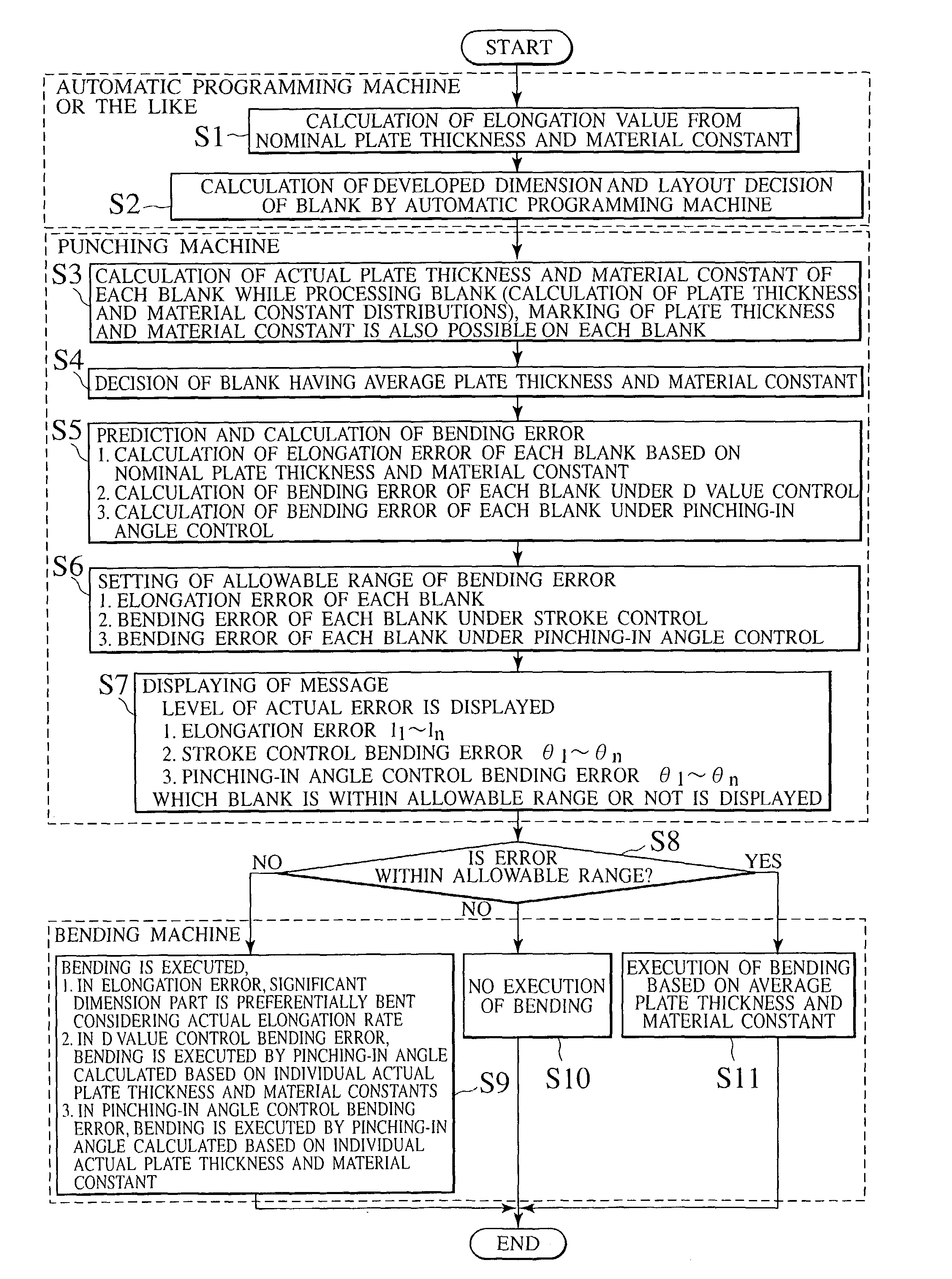
[0024]Thus, the actual plate thickness and the actual material constants of each blank can be efficiently and accurately measured during punching in blanking before bending. Therefore, this measured information can be reflected on bending, and efficient and accurate bending can be carried out.
[0046]Thus, since a bending error under control of the pinching-in angle of each blank can be calculated beforehand, blanking and bending along an actual situation are carried out depending on whether the bending error is within the allowable range or not. Thus, product accuracy and work efficiency during bending are improved, and the inspection time after bending is shortened.

Problems solved by technology

Consequently, a problem has been inherent, i.e., an actual bent dimension after bending is not within an allowable range.
For example, a problem has been inherent, i.e., even if a plate thickness of the blank is measured by the plate thickness detecting function during bending, the developed dimension of the blank that has been punched cannot be corrected.
Alternatively, a problem has occurred, i.e., correction of the blank necessitates time and labor of reprocessing.
Consequently, since a difference is generated in plate thickness of each blank, as described above, a problem has been inherent, i.e., a bent dimension is not within an allowable range.
However, unless the actual plate thickness or the actual material constant of the work is known before bending, it cannot be reflected on the developed dimension.

Method used


Image

  • Sheet working method, sheet working system, and various devices related to such system
  • Sheet working method, sheet working system, and various devices related to such system
  • Sheet working method, sheet working system, and various devices related to such system

Examples


Embodiment Construction

[0086]Next, description will be made of preferred embodiments of a method and a system for processing a plate material according to the present invention with reference to the accompanying drawings.

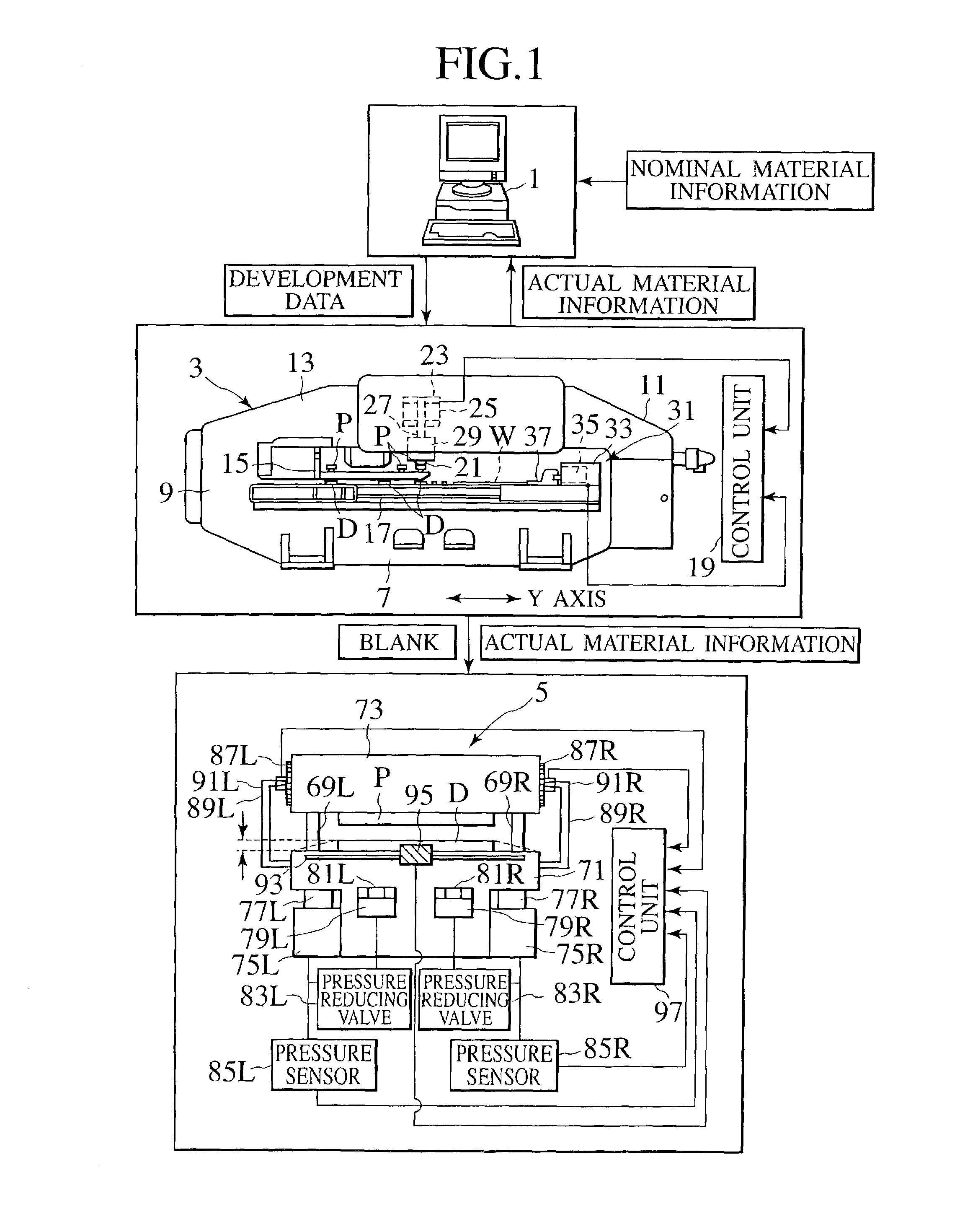
[0087]Referring to FIG. 1, a system of an embodiment for processing a plate material includes an automatic programming machine 1 for developing blanks based on a plate thickness, and material constant (tensile strength, Young's modulus, an n value, an f value or the like) of a work W, for example a turret punch press 3 as a punching machine for punching the work W by cooperative work between a punch P and a die D for blanking, and for example a press brake 5 as a bending machine for bending each blank punched by the turret punch press 3.

[0088]More specifically, for example, the above-described turret punch press 3 as the punching machine is formed in a frame structure, where both sides of an upper frame 13 are supported on side frames 9 and 11 erected on both sides of a base 7. Below the ...


PUM

PropertyMeasurementUnit
thicknessaaaaaaaaaa
thicknessaaaaaaaaaa
tensile strengthaaaaaaaaaa

Abstract

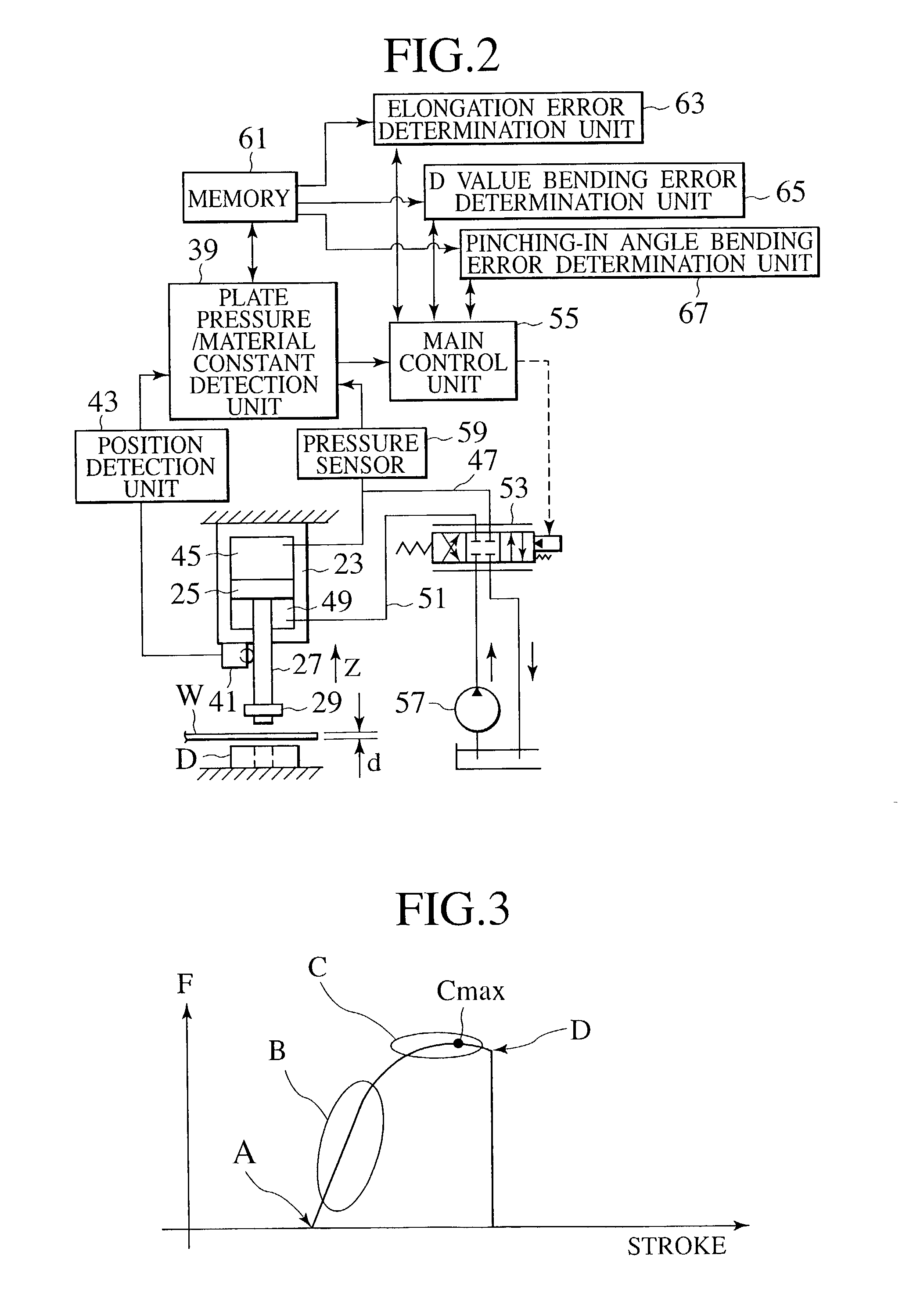
An actual plate thickness and actual material constants are measured during punching before bending. The measured information is reflected on the bending, so that the bending is performed efficiently and accurately. Punching is carried out for each blank developed based on a nominal plate thickness and nominal material constants in blanking before the bending of a work W. Then, an actual plate thickness distribution and an actual material constant distribution of the work W are calculated based on various data containing a ram stroke and a pressure detected in the punching.

Description

TECHNICAL FIELD[0001]The present invention relates to a method and a system for processing a plate material, and various devices concerning the system, and further relates to a method for calculating material attributes.BACKGROUND ART[0002]Conventionally, in the system for processing a plate material, a nominal value of a work, for example a material of SPCC, and a plate thickness of 1.6, is entered to an automatic programming machine. Based on this nominal value, an elongation value necessary for bending is calculated, and a developed dimension of a blank is calculated from this elongation value.[0003]In blanking work before bending, punching of the blanks is carried out by a punching machine based on the developed dimension. Each blank is bent by a bending machine.[0004]In the conventional system for processing a plate material, if a characteristic of a work to be actually processed is far from a nominal value, for example if an actual plate thickness is 1.5 mm while a nominal pla...

Claims


Application Information

Patent Timeline
Patent Type & Authority Patents(United States)
IPC IPC(8): B21C51/00B21D28/00B30B15/00G01B21/08B21D5/02B21D28/12B21D28/24G01B21/00
CPCB21D5/02B21D28/24B21D28/12Y10S72/702
Inventor KOYAMA, JUNICHIOMATA, HITOSHIHAYAMA, OSAMUIMAI, KAZUNARITAKEHARA, TOKUROANZAI, TETSUYA
Owner AMADA CO LTD
Learn More