Method and system for non-destructive inspection of a colony of stress corrosion cracks

a stress corrosion crack and colony technology, applied in the direction of mechanical roughness/irregularity measurement, applications, instruments, etc., can solve the problems of inability to accurately measure no reliable and widely accepted assessment tools exist for evaluation, and no reliable and widely accepted tools exist for measuring the depth of the crack

Inactive Publication Date: 2010-05-27
ROENTGEN TECHNISCHE DIENST BV
View PDF23 Cites 24 Cited by
  • Summary
  • Abstract
  • Description
  • Claims
  • Application Information

AI Technical Summary

Benefits of technology

[0012]It is an object of the present invention to provide an improved method for non-destructive inspection of a colony of stress corrosion cracks.
[0013]Accordingly, the invention provides a method for non-destructive inspection of a colony of stress corrosion cracks in a pipe or a vessel, comprising mapping the colony of stress corrosion cracks, identifying at least one individual crack to be sized within the colony, and sizing the at least one individual crack to be sized. Herein “sizing” refers to determining a depth of the crack. This method provides the advantage that the depth of one individual crack within the colony of stress corrosion cracks can be determined without interference from surrounding cracks within the colony. This provides a more accurate representation of the depth profile of the crack(s) identified to be sized within the colony of stress corrosion cracks, thereby enabling the prediction of the remaining strength of the affected pipe or vessel, e.g. the pipe or vessel comprising carbon steel or stainless steel. Moreover, the measured value of the depth of the individual crack allows calculation of the failure pressure of the colony.
[0020]In an embodiment, the method is practised on a volume of solid material that comprises a metal, such as a volume of a metal pipeline, the mapping step comprises performing a method of non-destructive inspection along a surface of the volume of solid material (e.g. electromagnetic inspection), for determining the defect pattern and / or distribution along the surface, and the sizing step comprises performing a method of ultrasonic inspection determining a depth of an individual crack associated with a defect of the defect pattern. By using this method, a rather quick overview of defects can be obtained in the mapping step, whereafter an individual defect or set of defects can be sized with high accuracy in the sizing step. The method may thus integrate the advantages of electromagnetic inspection and ultrasonic inspection into a powerful inspection method.
[0022]Preferably, the mapping, e.g. the electromagnetic inspection, and the sizing, e.g. the ultrasonic inspection, are carried out as a combined scan step, for example substantially at the same time or substantially without waiting time between both methods. Each one of such spatial and temporal limitations on performing the sizing and / or the mapping reduce the inspection time of the method according to the invention.

Problems solved by technology

While the number of incidents attributed to SCC is less than those attributed to other threats to pipelines such as corrosion or mechanical damage, it constitutes a challenge due to the following reasons:
no reliable, accurate and industry-accepted in-line-inspection tools or predictive modelling based tools exist that are capable of determining what locations along the pipeline are affected by SCC;
no reliable and widely accepted assessment tools exist for evaluation of SCC, once found; and
no reliable and widely accepted tools exist that are capable of measuring the depth of these cracks accurately.
Given these limitations, development of an effective SCC mitigation plan and assessment techniques has been slow.
Recent developments in Inline Inspection (ILI) technology and increasing understanding of the phenomenon seem to show promise, but the lack of a reliable non-destructive means for measuring crack depths within an SCC colony makes it difficult to develop a comprehensive approach.
Currently, there are no standard practices for managing SCC.
While several methods have been suggested for calculating the failure pressure, none of the methods have had extensive validation using full-scale burst tests and therefore, are not widely used.
No widely acceptable, proven and reliable non-destructive technology exists that is capable of measuring the depth (sizing) of SCC.
The lack of non-destructive sizing technology is also responsible for the lack of a validated SCC evaluation method.

Method used


Image

  • Method and system for non-destructive inspection of a colony of stress corrosion cracks
  • Method and system for non-destructive inspection of a colony of stress corrosion cracks
  • Method and system for non-destructive inspection of a colony of stress corrosion cracks

Examples


Embodiment Construction

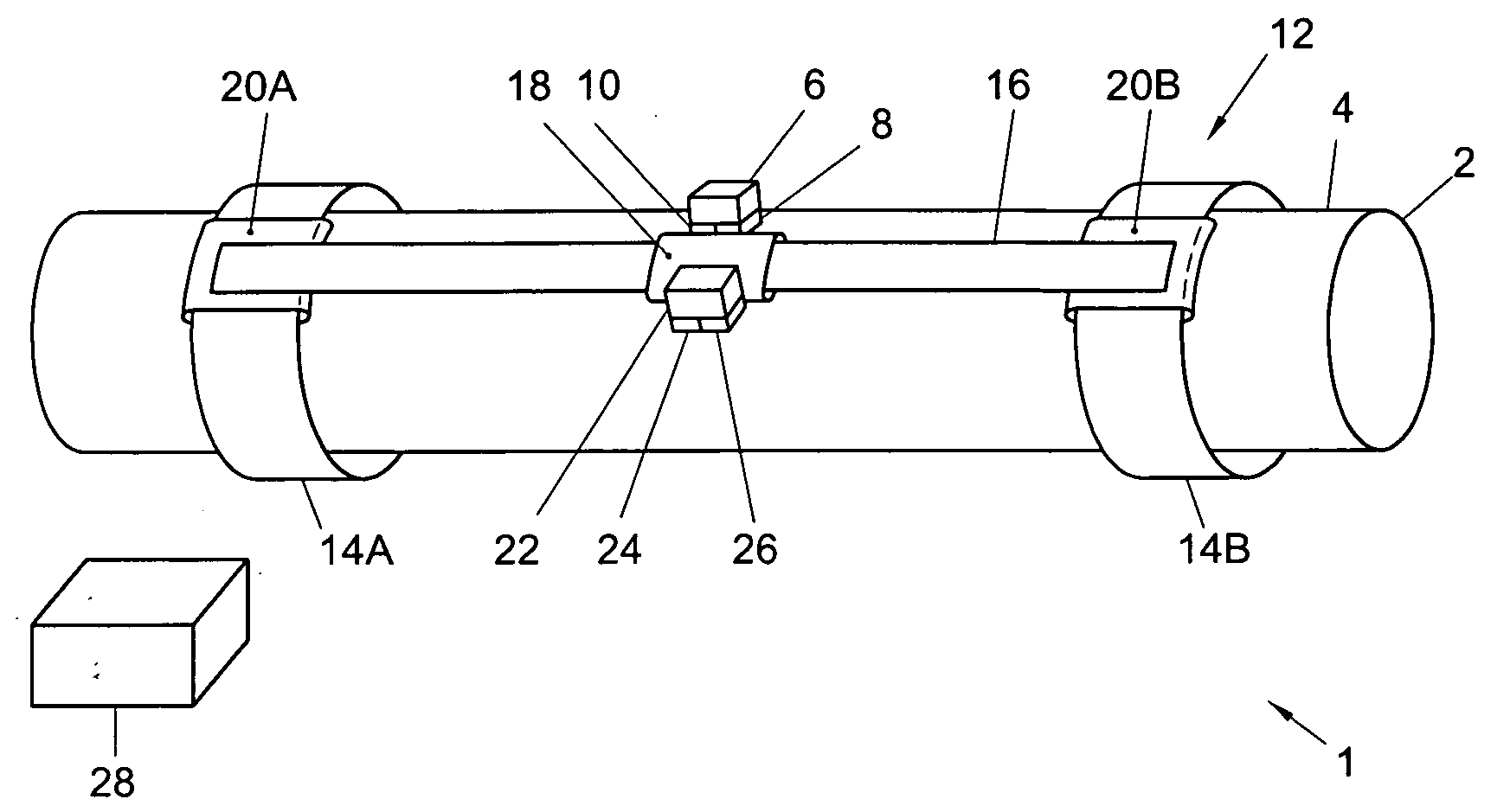
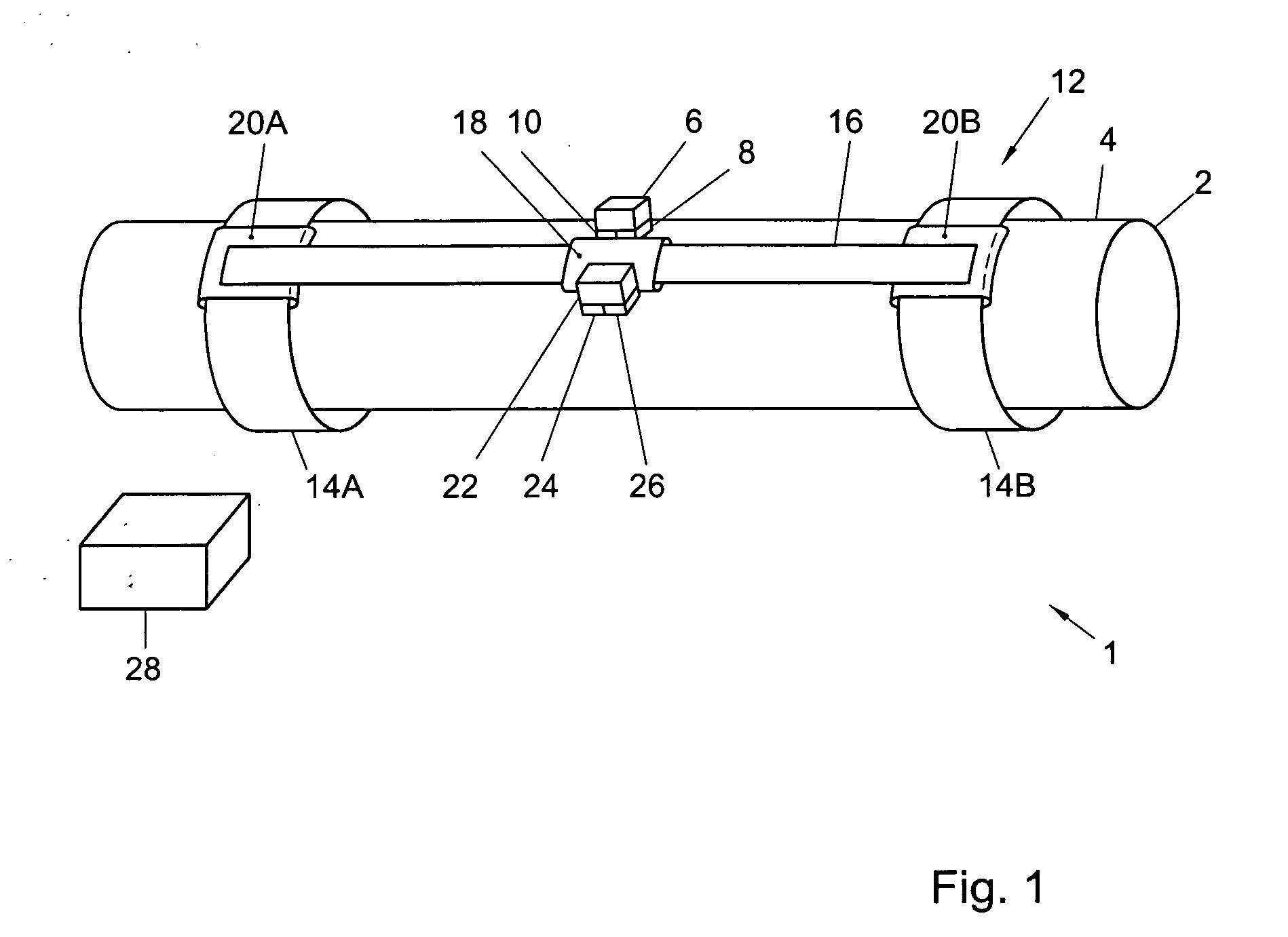
[0040]FIG. 1 shows a schematic representation of an embodiment of an inspection system 1 for non-destructive inspection of a colony of stress corrosion cracks in an object. In this example the object is a carbon steel or stainless steel pipe 2. The pipe may e.g. be part of a pipeline, such as a pipeline for natural gas or crude oil. The object may also be a vessel such as a column or storage tank, e.g. in a chemical plant. The object in this example thus has a steel wall 4.

[0041]The inspection system 1 comprises a mapping detector 6 for mapping the colony of stress corrosion cracks. In this example, the mapping detector 6 comprises an electromagnetic mapping detector comprising a first electromagnetic transducer 8 for applying an electromagnetic field in the steel wall 4, and a second electromagnetic transducer 10 for receiving a resulting electromagnetic response of the steel wall 4. The electromagnetic mapping detector 6 is arranged for outputting mapping data representative of th...


PUM

PropertyMeasurementUnit
pulse energyaaaaaaaaaa
wavelengthaaaaaaaaaa
frequencyaaaaaaaaaa

Abstract

The invention relates to a method and inspection system for non-destructive inspection of a colony of stress corrosion cracks in a pipe or a vessel. The method comprises mapping the colony of stress corrosion cracks, identifying at least one individual crack to be sized within the colony, and sizing the at least one individual crack to be sized.

Description

[0001]The invention relates to a method for non-destructive inspection of a colony of stress corrosion cracks in a pipe or vessel. The invention also relates to an inspection system for carrying out a method according to the invention.BACKGROUND OF THE INVENTION[0002]Several pipeline failures around the world have been attributed to Stress Corrosion Cracking (SCC) since its discovery in pipelines in the 1960's including USA, Canada, Russia, France, Saudi Arabia, Australia and South America. While the number of incidents attributed to SCC is less than those attributed to other threats to pipelines such as corrosion or mechanical damage, it constitutes a challenge due to the following reasons:[0003]no reliable, accurate and industry-accepted in-line-inspection tools or predictive modelling based tools exist that are capable of determining what locations along the pipeline are affected by SCC;[0004]no reliable and widely accepted assessment tools exist for evaluation of SCC, once found...

Claims


Application Information

Patent Timeline
Patent Type & Authority Applications(United States)
IPC IPC(8): G01N27/20G01N29/04G01M99/00
CPCG01N27/90G01N29/0672G01N2291/2634G01N29/265G01N29/2418
Inventor FINGERHUT, MARTINTOMAR, MUNENDRAKLEIN, MARVIN
Owner ROENTGEN TECHNISCHE DIENST BV
Why Eureka
Try Eureka