Multi-channel electro-acoustic transfer function measurement method

A technology of transfer function and measurement method, applied in electrical components and other directions, which can solve the problems of comparable measurement accuracy and time-consuming

Active Publication Date: 2013-07-17
TSINGHUA UNIV
View PDF3 Cites 6 Cited by
  • Summary
  • Abstract
  • Description
  • Claims
  • Application Information

AI Technical Summary

Problems solved by technology

However, the frequency sweep signal method is still time-consuming when measuring the multi-channel transfer function, and when using the correlation method, it ofte

Method used


Image

  • Multi-channel electro-acoustic transfer function measurement method
  • Multi-channel electro-acoustic transfer function measurement method
  • Multi-channel electro-acoustic transfer function measurement method

Examples


Embodiment Construction

[0064] The specific implementation manners of the present invention will be described in detail below in conjunction with the accompanying drawings.

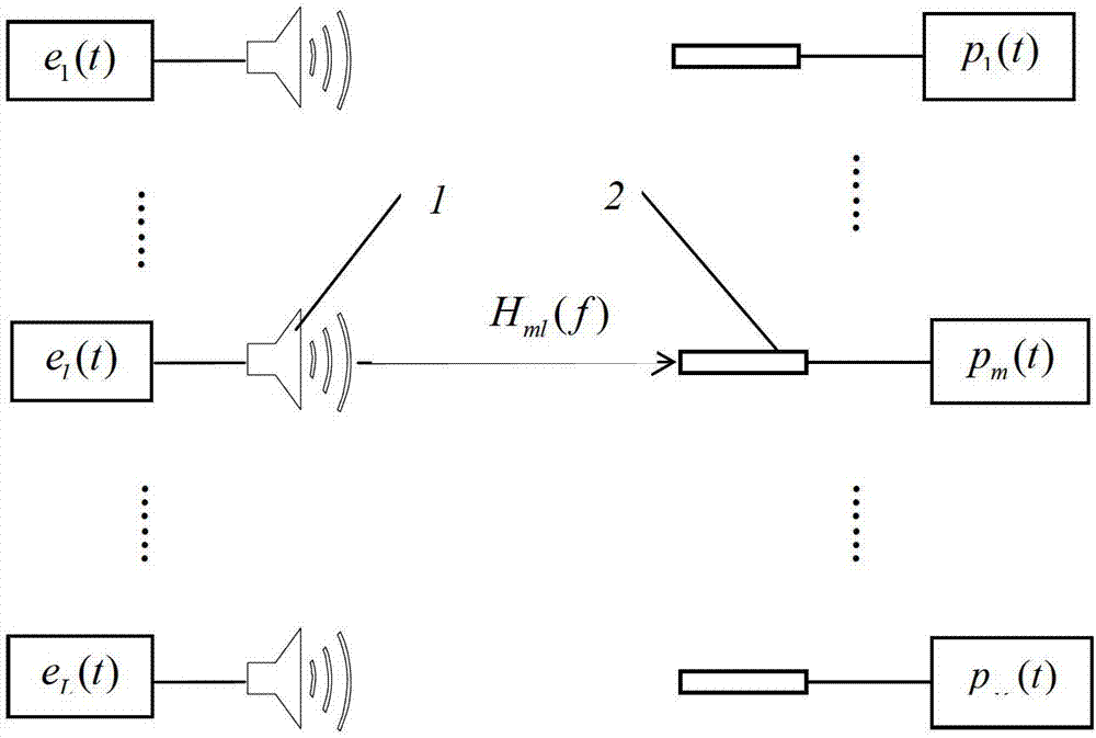
[0065] The measurement method and implementation of the multi-channel electroacoustic transfer function proposed by the present invention, such as figure 1 As shown, an electro-acoustic transmission system is composed of L loudspeakers 1 and M microphones 2 arranged in a space (this space can be a free boundary space or a reflection boundary; in this embodiment, L=18, M =20). For any loudspeaker l in the electroacoustic transfer function system, its excitation electric signal e l (t) Individual control; the sound emitted by each speaker is measured simultaneously by M microphones, and the sound pressure signal measured by the m microphone is p m (t); speaker excitation electrical signal e l (t) and the sound pressure signal p measured by the microphone m The transitive relationship between (t) is defined as a transfer funct...


PUM


Abstract

The invention relates to a multi-channel electro-acoustic transfer function measurement method and belongs to the technical field of electro-acoustic transfer function measurement. The multi-channel electro-acoustic transfer function measurement method includes that L loudspeakers and M microphones are arranged in a space to form an electro-acoustic transfer system; any one loudspeaker l in the electro-acoustic transfer system is independently controlled by an excitation electric signal el (t) of the loudspeaker l; sounds generated by all the loudspeakers are obtained through simultaneous measurement of the M microphones, and the mth microphone measures a sound pressure signal pm (t); the transfer relation between the loudspeaker excitation electric signal el (t) and the sound pressure signal pm (t) measured by the microphone is defined to be a transfer function; and the loudspeaker excitation electric signal el (t) controls the loudspeakers to generate sounds, and the transfer function is calculated by measuring the sound pressure signal pm (t) and the loudspeaker excitation electric signal el (t). The multi-channel electro-acoustic transfer function measurement method is comparable to a simple-frequency signal method in measurement accuracy, and simultaneously has the advantage of high efficiency.

Description

technical field [0001] The invention belongs to the technical field of electroacoustic transfer function measurement, in particular to a method for measuring and calculating the electroacoustic transfer function from multi-channel audio signals to multi-point positions in space. Background technique [0002] Electroacoustic transfer function has been widely used in the field of acoustics. The transfer function refers to the excitation electrical signal from the loudspeaker e l (t) and the sound pressure signal p received by the microphone m The frequency-domain transfer relationship between (t), there is a relationship between them as shown in formula (1): [0003] P m (f)=H ml (f)E l (f) (1) [0004] In formula (1), E l (f) is the excitation electrical signal e of the lth speaker l (t) magnitude spectrum, P m (f) is the sound pressure signal p measured by the mth microphone m (t) magnitude spectrum, H ml (f) for E l (f) and P m (f) transfer function between. W...

Claims


Application Information

Patent Timeline
IPC IPC(8): H04R29/00
Inventor 郑四发连小珉彭博李申广廖祥凝杨殿阁李克强
Owner TSINGHUA UNIV
Why Eureka
Try Eureka