Hinge cap

a hinge and cap technology, applied in the field of hinge caps, can solve the problems of inmates hanging or abusing themselves from the protruding surface of hinges, injury or death, and the door is not connected to the frame to which the door is attached,

Active Publication Date: 2014-12-02
SELECT PRODS
View PDF13 Cites 3 Cited by
  • Summary
  • Abstract
  • Description
  • Claims
  • Application Information

AI Technical Summary

Benefits of technology

[0004]It is an object of the present invention to provide a practical economical solution to a serious problem associated with misuse of the top surface of continuous geared door hinges. It is a further object of the present invention to provide a means and a method for covering or overlaying the top surface of a continuous geared door hinge to prevent hanging objects on the hinge as well as to prevent individuals from using the hinge for abusive purposes.
[0005]The present invention accomplishes these purposes and makes rooms safer while meeting legal requirements by retrofitting door hinges to deter patients or inmates from harming themselves by using the top of the hinge to hang or abuse themselves. It also helps to prevent the accidental prying of the hinge and door from the frame when objects are hung from the hinge.
[0006]The present invention comprises a means and a method including a five sided block for mounting on a frame for a door, the block having a downwardly angled front side, a back side, a bottom side and two ends, said back and bottom sides being substantially at right angles to each other, said bottom side being shaped and sized to cover an exposed top surface of an installed continuous geared door hinge, said ends being triangular in cross section, said front surface having at least one counterbored hole that extends from the front side to the back side and is suitable for mounting said block on the surface of a frame for the door using a security type screw having a head that can be recessed far enough into the larger portion of the counterbored hole on the front side to avoid interfering with the downwardly angled front side. The said block is preferably constructed using a hard durable material such as plastic, metal or fiberglass to minimize tampering or destruction. The said block preferably has one counterbored hole for attachment to the frame over an installed door hinge with a narrow top surface (such as a mortise type continuous geared hinge) and having two counterbored holes for attachment to the frame over an installed door hinge with a wide top surface (such as a full surface continuous geared hinge). The angle of the front surface should be steep, preferably from about 40% to about 50% measured from the plane of the bottom side. The head of the screw used to attach the block is preferably configured to require a special tool to tighten or remove the screw. The said block preferably has rounded edges to the extent they are exposed after installation to minimize possible abuse. Using the security screws the blocks are attached to the frame of a door just over the position occupied by the top surface of an installed hinge when the door is closed leaving no part of the top surface exposed. Some overlap over the top surface of the hinge is permissible if the exposed edges of the block are rounded. The present invention includes a method of deterring a person from hanging objects or abusing him or herself on the exposed top surface of a continuous geared door hinge installed on a door, the method comprising the step of affixing a block that is shaped, sized and positioned on a door frame so as to overlay the top surface of the hinge when the door is closed without providing an exposed surface that has sharp edges or permits a person to hang objects from the block.
[0011]The block of the present invention can be machined, molded, extruded or forged to produce the desired shapes. Molding using a plastic material is preferred for overall economy.

Problems solved by technology

Much to the dismay of hinge manufacturers humans find ways to use hinges for other than their intended uses, for example, by hanging objects or abusing themselves on protruding surfaces of the hinges.
Such uses can lead to unhinging the door from the frame to which the door is attached or, more surprisingly, to injury or death, particularly to inmates of institutions like prisons or mental hospitals where more irrational persons are housed.
Likewise in prisons and mental institutions inmates have been known to hang or abuse themselves from the protruding surfaces of hinges.
These are not theoretical possibilities.
Like all serious problems, the challenge is always to find a solution that is both practical and economical.
In this case where misbehavior is involved, the first reaction would be to take steps to change the behavior, always difficult to do.

Method used


Image

  • Hinge cap
  • Hinge cap
  • Hinge cap

Examples


Embodiment Construction

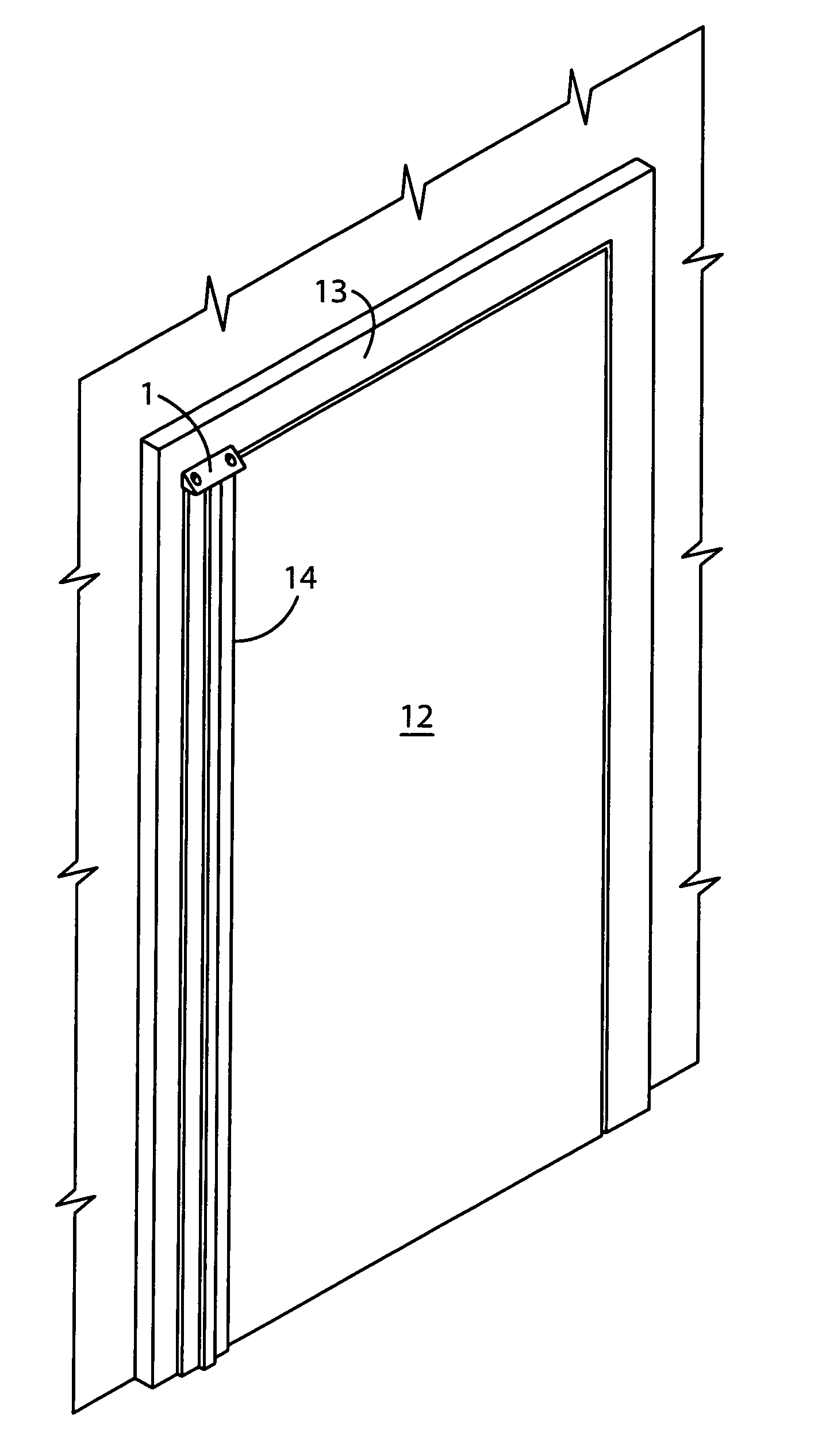
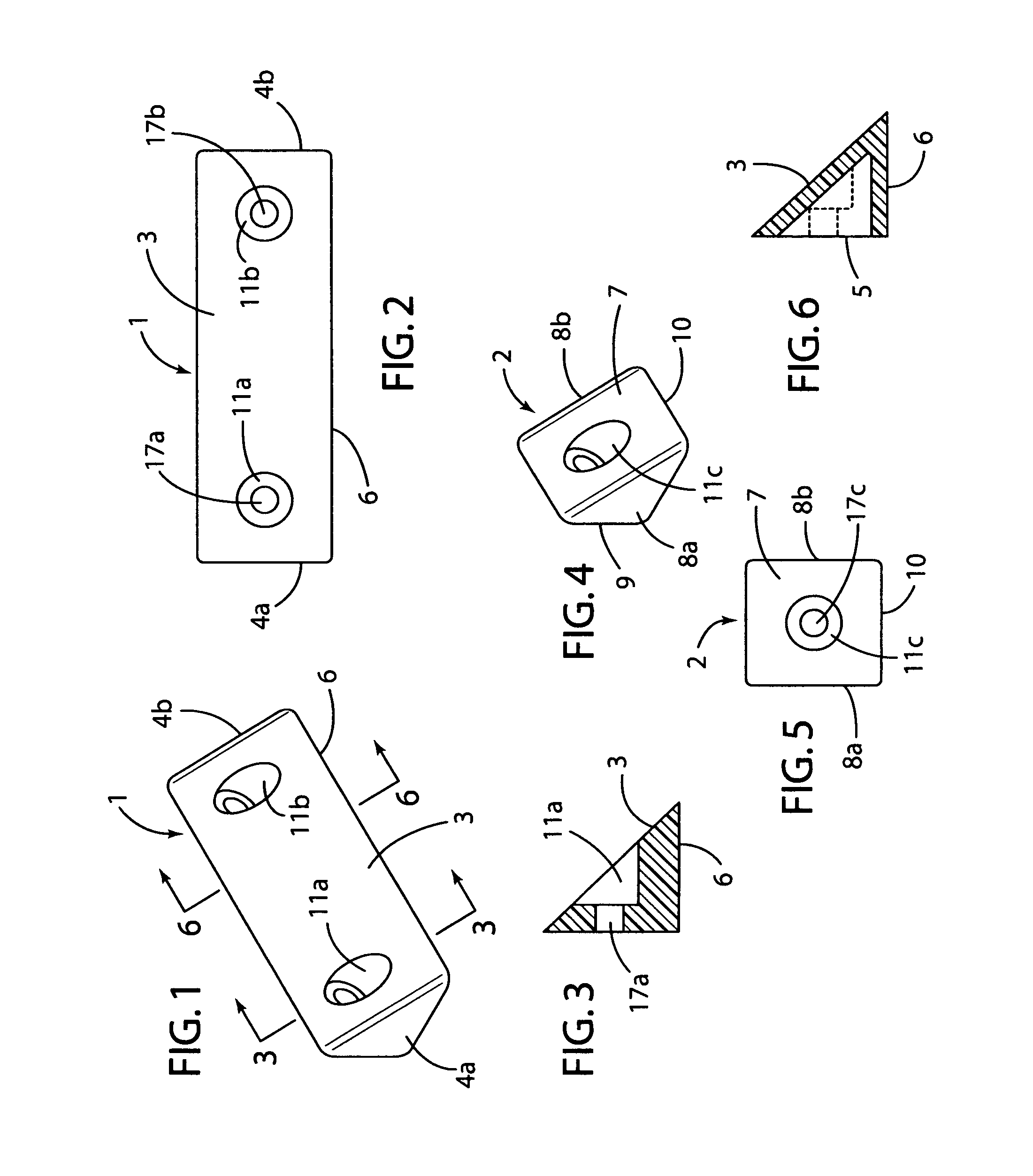
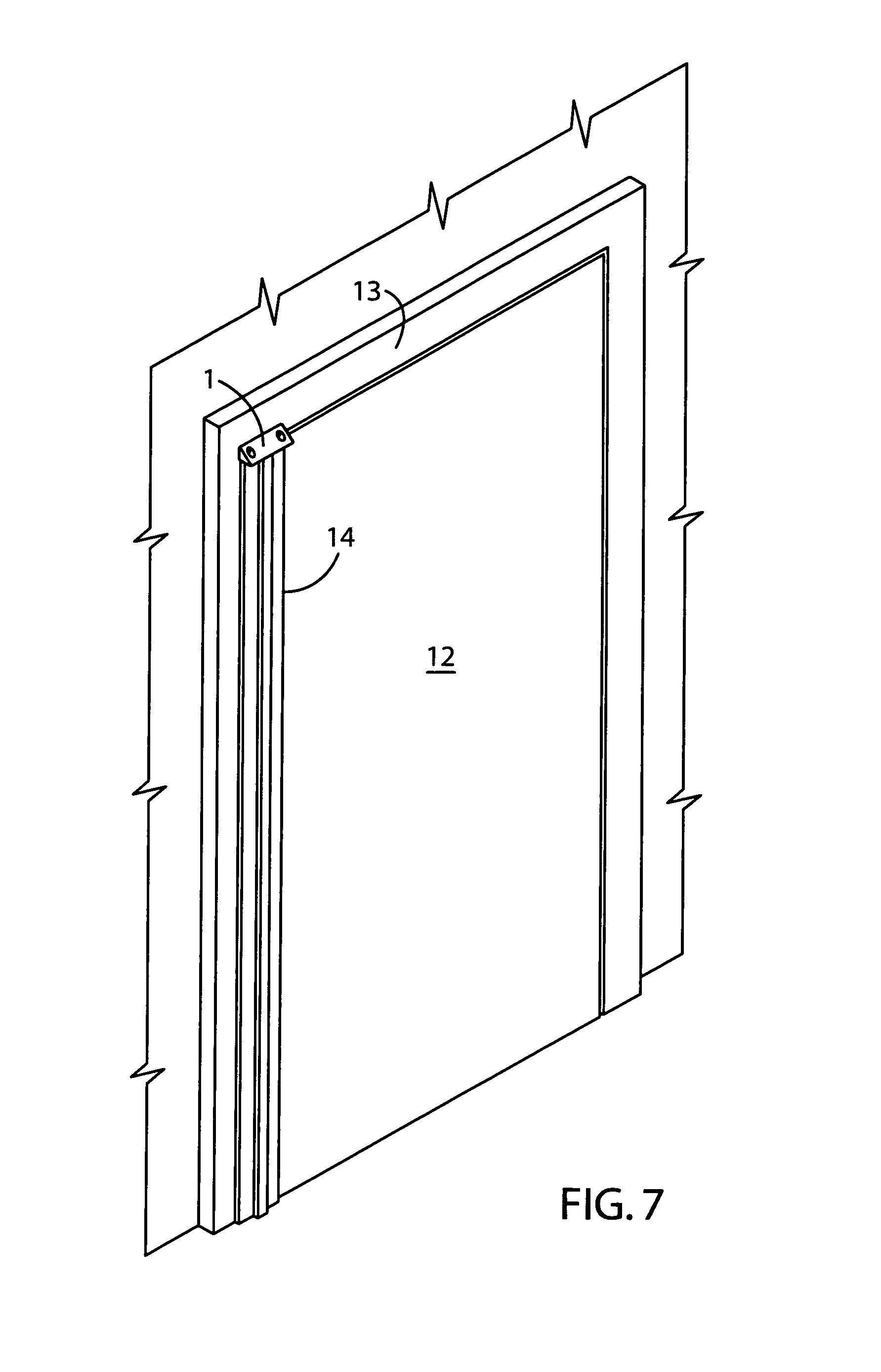
[0037]The preferred embodiments of the product of the present invention consist of the versions of the block best shown in FIGS. 1 and 4.

[0038]The essential components of the above embodiments 1,2 of the block include:

[0039](1) A downward sloping front side 3,7,

[0040](2) A bottom surface 6,10 adapted for covering the unobstructed top surface of a continuous geared hinge,

[0041](3) A back side 5,9 perpendicular to the bottom side 6,10 and

[0042](4) At least one counterbored hole extending from the front side 3,7 through the back side 5,9 adapted for mounting the block 1,2 to a frame 13 for a door 12 with a security type screw (not shown) without obstructing the slope of the front side 3,7.

[0043]The block 1,2 can be machined, molded, extruded or forged to shape using conventional manufacturing techniques. A molded plastic version of the block 1,2 is preferred because of ease and economy of manufacture. The preferred plastic material is a polyester resin such as VALOX 310 SEO, a polybuty...


PUM


Abstract

A product and a method employing a block having a downwardly angled front surface suitable for covering the top surface of a continuous geared door hinge after the door is installed in a frame. The block has one or more recessed counter bored holes in the front surface to accommodate security screws without compromising the angle of the front surface.

Description

[0001]This application claims the benefit under 34 U.S.C. 119(c) of provisional application No. 61 / 231,249 filed Aug. 4, 2009 entitled “A STEEPLY ANGLED BLOCK TO DETER HANGING OBJECTS FROM A DOOR HINGE BARREL OR COVER”.BACKGROUND OF THE INVENTION[0002]Door hinges are primarily designed to facilitate opening, closing and securing the door. To the extent safety or security is a concern, both the patent literature and hinge manufacturers focus on preventing fingers from being caught between the door and the jamb or preventing entry by unwanted intruders into areas partially protected by doors. In psychiatric wards and criminal detention facilities hinges are also designed to prevent exiting out of the doors.[0003]Much to the dismay of hinge manufacturers humans find ways to use hinges for other than their intended uses, for example, by hanging objects or abusing themselves on protruding surfaces of the hinges. Such uses can lead to unhinging the door from the frame to which the door is...

Claims


Application Information

Patent Timeline
Patent Type & Authority Patents(United States)
IPC IPC(8): E05D11/00
CPCE05Y2900/132E05D11/0054Y10T16/61Y10T16/533
Inventor SCHAU, TIMOTHY ALAN
Owner SELECT PRODS
Why Eureka
Try Eureka