Constant temperature control device

a constant temperature control and control device technology, applied in temperatue control, process and machine control, instruments, etc., can solve the problems of assembly cost, inconvenient maintenance and replacement, and the constant temperature control device cannot be operated normally, so as to save maintenance and replacement cost, easy maintenance and replacement, and poor connection

Active Publication Date: 2013-02-21
GLOBE UNION INDAL
View PDF10 Cites 6 Cited by
  • Summary
  • Abstract
  • Description
  • Claims
  • Application Information

AI Technical Summary

Benefits of technology

[0022]Because the base is engaged with or disengaged from the two projections and an indentation by using the two hooks and the positioning block respectively, the stainless steel piece, the springs, and the plugs are maintained and replaced easily without replacing the constant temperature control device completely to save maintenance and replacement cost.
[0023]Due to the operating shaft includes the cooper member to form the extension and the plastic member integrally covered on the bottom end of the cooper member to form the disk, a connecting cost of the cooper member and the plastic member is saved and a poor connecting problem thereof s avoided.
[0024]In addition, the first inflow orifice and the second inflow orifice of the pressure balanced valve are provided with two check valves individually so that the constant temperature control device are shifted from a water turn-on state to a water turn-off state so that the cold water and the hot water will not flow back to the first channel or the second channel from the pressure balanced valve, thereby preventing from a water hammer.

Problems solved by technology

However, a base of the constant temperature control device is retained with a covering member, when the first ceramics member and the second ceramics member are broken after being used for a period of time, the constant temperature control device can not be operated normally and has to be replaced, thereby having an inconvenient maintenance and replacement.
The lever of the constant temperature control device is comprised of a plurality of components worked in advance and then connected together, having an assembly cost.
Nevertheless, such a conventional temperature control device can not guide the mixed water to flow toward the faucet, so when the showering equipment is in a water supply state of the faucet, one part of mixed water from the temperature control device flows toward the shower head still, having a water leak from the shower head.
Moreover, while the water supply is closed, the cold water and the hot water in the mixed room flow back to a first hole to flow the cold water and a second hole to flow the hot water of the mixed room to generate water hammer, thereby having a noise.

Method used


Image

  • Constant temperature control device
  • Constant temperature control device
  • Constant temperature control device

Examples


Embodiment Construction

[0039]The present invention will be clearer from the following description when viewed together with the accompanying drawings, which show, for purpose of illustrations only, the preferred embodiment in accordance with the present invention.

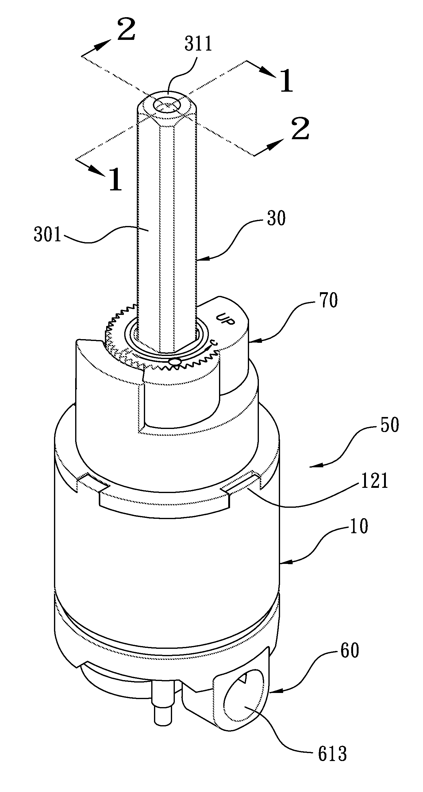
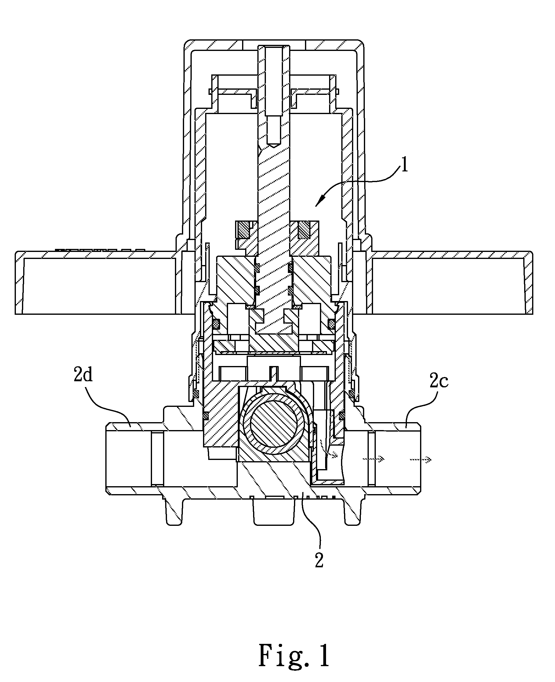
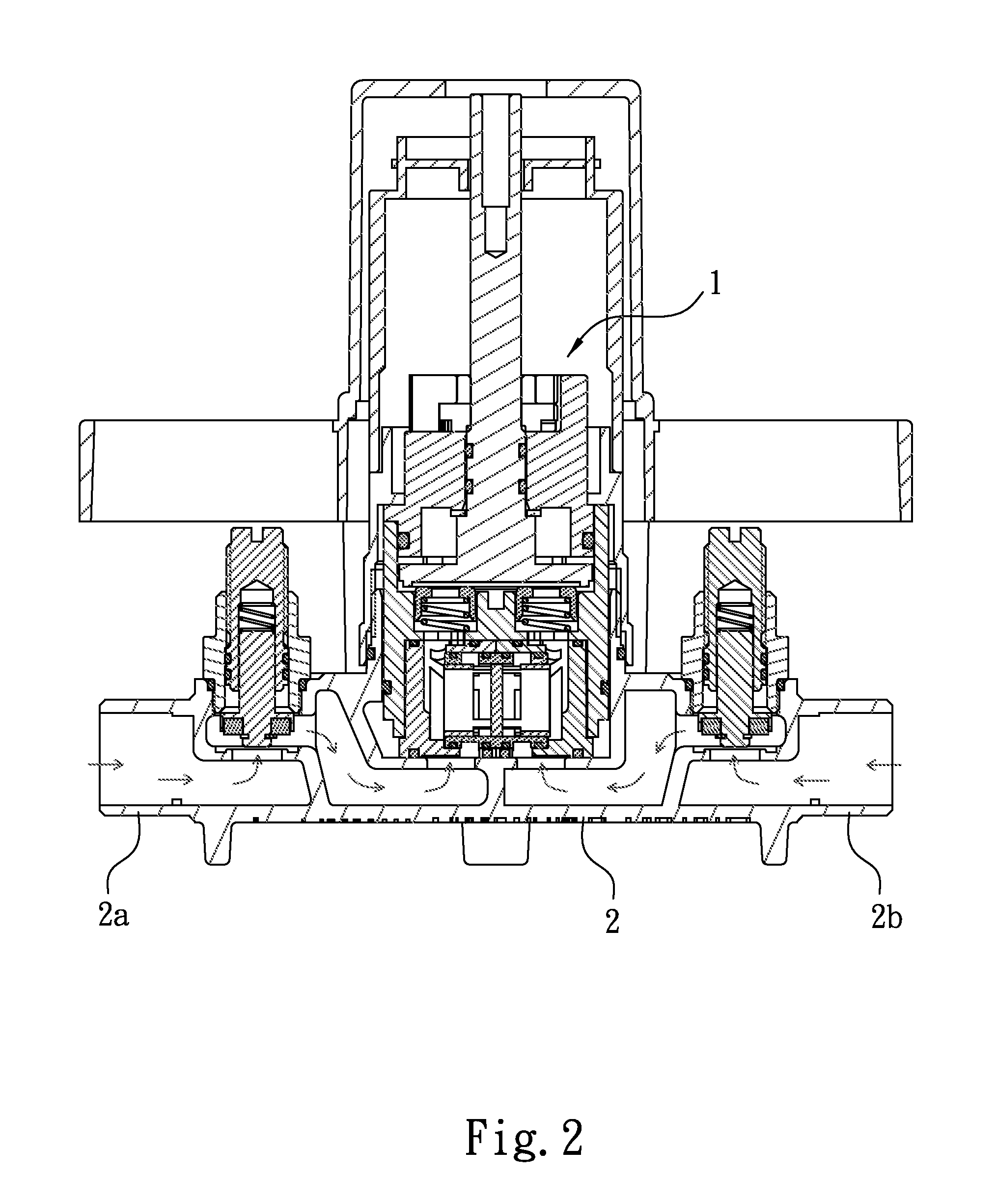
[0040]Referring to FIGS. 1-3, a constant temperature control device 1 according to a first embodiment of the present invention is a pressure balance type of constant temperature control device and is fixed in a cross pipe member 2 of a showering equipment, the pipe member 2 includes a first channel 2a to flow cold water into the constant temperature control device 1 and a second channel 2b to flow hot water into the constant temperature control device 1, and the first channel 2a and the second channel 2b are spaced apart from each other, the pipe member 2 also includes a first outlet passage 2c and a second outlet passage 2d; wherein the first outlet passage 2c is connected with a faucet and includes a lever to distribute water disposed thereon s...


PUM


Abstract

A constant temperature control device contains a base including a central wall and a peripheral wall to define a chamber; the peripheral wall including a tunnel and hooks; the central wall including a first and a second holes and two grooves; a pressure balanced valve engaged in the chamber and including a first and a second inflow orifices and a first and a second outflow orifices; a controlling assembly including an operating shaft and a stainless steel piece; two plug sets, each including two springs and two stoppers, and each stopper including an aperture; a covering member including projections and a pore; between the covering member and the disk being defined with a second cavity; an outlet member fixed in the tunnel of the base and including a twisted passageway arranged therein so that the mixed water flows vertically from the tunnel and then is guided to jet horizontally.

Description

BACKGROUND OF THE INVENTION[0001]1. Field of the Invention[0002]The present invention relates to a constant temperature control device with a pressure balanced valve.[0003]2. Description of the Prior Art[0004]Conventional constant temperature control device with a pressure balanced valve is used in a showering equipment and includes a handle to drive a lever to rotate a first ceramics member and a second ceramics member, because the first ceramics member includes an inflow room and a close wall, when the handle is in a close state, cold water and hot water flow into a first hole and a second hole of the second ceramics member respectively via the pressure balanced valve, and the cold water and the hot water are closed by the close wall without flowing outward.[0005]When the handle is rotated, the inflow room of the first ceramics member is rotated to communicate with the first hole and the second hole of the second ceramics member so that the cold water flows into an inlet channel o...

Claims


Application Information

Patent Timeline
Patent Type & Authority Applications(United States)
IPC IPC(8): F15D1/00
CPCF15D1/04F16K19/006G05D23/1313Y10T137/2521Y10T137/86815
Inventor YAN, LIGUO
Owner GLOBE UNION INDAL
Why Eureka
Try Eureka