Liquid crystal display apparatus and driving method thereof

a display apparatus and liquid crystal technology, applied in the direction of non-linear optics, static indicating devices, instruments, etc., can solve the problems of poor display quality and horizontal crosstalk phenomenon of displayed images, and achieve the effect of mitigating horizontal crosstalk phenomenon

Inactive Publication Date: 2010-12-09
HANNSTAR DISPLAY CORPORATION
View PDF5 Cites 5 Cited by
  • Summary
  • Abstract
  • Description
  • Claims
  • Application Information

AI Technical Summary

Benefits of technology

[0010]The present invention is directed to a liquid crystal display (LCD) apparatus, which can greatly mitigate a horizontal crosstalk phenomenon.

Problems solved by technology

When the transmissive area T1 and the reflective area R1 display an image of a same pixel voltage, luminance / gray levels of the displayed image are inconsistent, so that a display quality is poor.
However, when the active device 226T is deactivated, the compensation capacitor CCA presents a floating state, which may lead to a horizontal crosstalk phenomenon of the displayed image.

Method used


Image

  • Liquid crystal display apparatus and driving method thereof
  • Liquid crystal display apparatus and driving method thereof
  • Liquid crystal display apparatus and driving method thereof

Examples


first embodiment

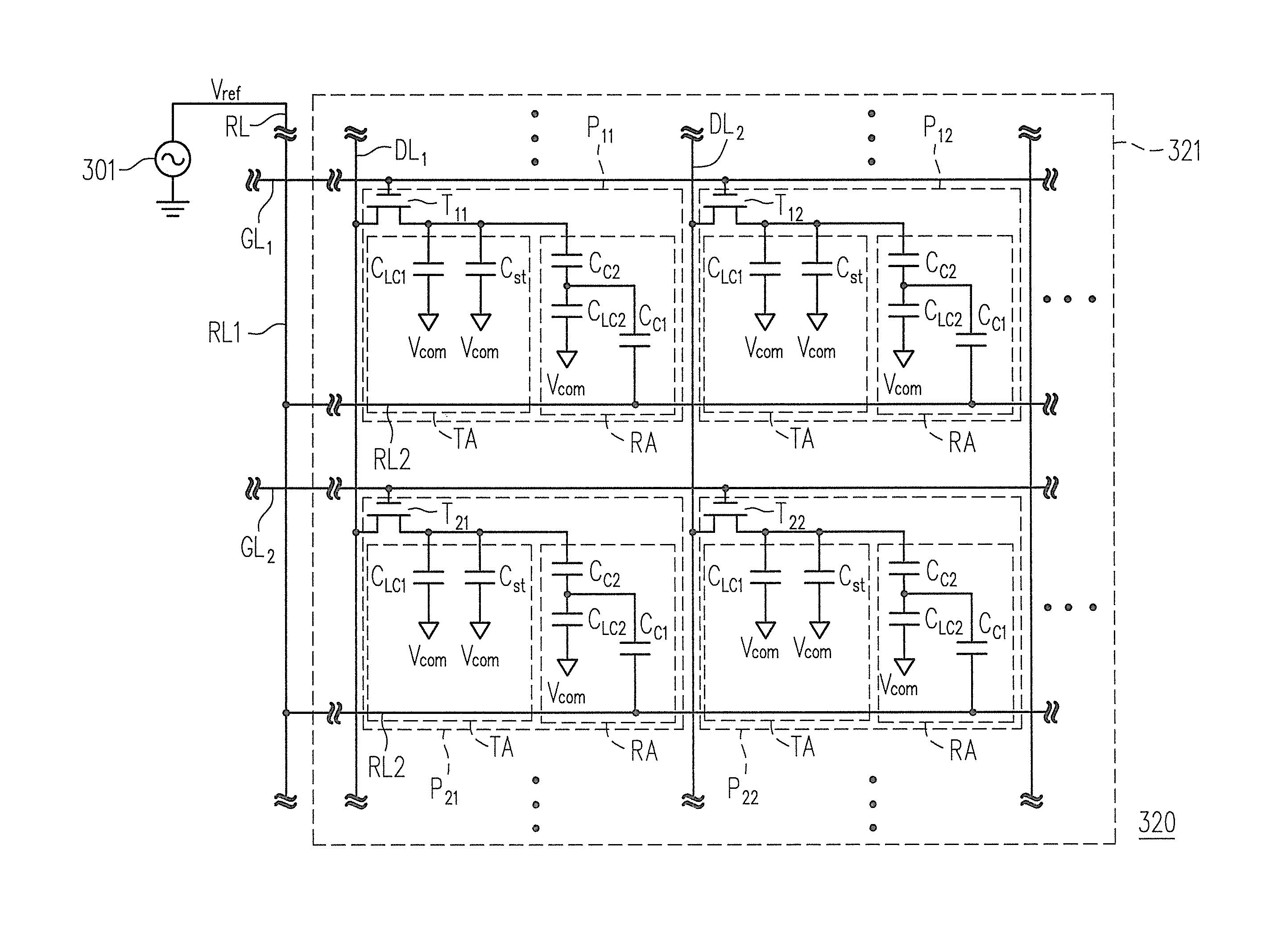
[0041]FIG. 4 is a partial equivalent circuit diagram of a display panel 320 in a transflective liquid crystal display (LCD) apparatus according to an embodiment of the present invention. It should be noticed that besides the display panel 320, the transflective LCD apparatus further includes other components of a general display apparatus, for example, a control panel, a gate driver, a source driver, a power generator, and a backlight module, etc., which are all not illustrated. For simplicity's sake, a coupling method between these components and the display panel 320, and descriptions of functions of the components are omitted, and only designs related to the present invention are illustrated and described.

[0042]Referring to FIG. 4, the display panel 320 of the present embodiment includes a plurality of scan lines GL1, GL2, . . . , a plurality of data lines DL1, DL2, . . . , and a plurality of pixel structures P11, P12, P21, P22, . . . to foam a plurality of pixel units. An area w...

second embodiment

[0072]The spirit of the present embodiment is similar to that of the first embodiment. However, in the present embodiment, the second pixel area of each of the pixel structures further includes another reflective area RA2 as that shown in FIG. 7, wherein only one pixel unit is illustrated in FIG. 7. Moreover, like reference numerals in the present embodiment and the first embodiment refer to the same or like elements, and therefore detailed descriptions thereof are not repeated.

[0073]FIG. 7 is a partial equivalent circuit diagram of a display panel according to the second embodiment of the present invention. Referring to FIG. 7, each of pixel structures P in the display panel 720 of the present embodiment has a first pixel area and a second pixel area, wherein the first pixel area includes a transmissive area TA1, and the second pixel area includes a first reflective area RA1 and a second reflective area RA2.

[0074]In the present embodiment, a liquid crystal capacitor in the transmis...


PUM

PropertyMeasurementUnit
voltageaaaaaaaaaa
signal polaritiesaaaaaaaaaa
polarityaaaaaaaaaa

Abstract

An LCD apparatus and a driving method thereof are provided. The LCD apparatus includes a reference voltage line and a display area including scan lines, data lines and pixel structures. Each pixel structure is electrically connected to the corresponding scan/data line, and has a first pixel area and a second pixel area. The first pixel area includes a first liquid crystal capacitor with one end electrically connected to a common voltage. The second pixel area includes a second liquid crystal capacitor and a first compensation capacitor. One end of the second liquid crystal capacitor is electrically connected to the common voltage, one end of the first compensation capacitor is electrically connected to the second liquid crystal capacitor and another end is electrically connected to a reference voltage source through the reference voltage line. The reference voltage source provides a reference voltage having a continuous periodic signal or a time-varying signal.

Description

CROSS-REFERENCE TO RELATED APPLICATION[0001]This application claims the priority benefit of Taiwan application serial no. 98118790, filed on Jun. 5, 2009. The entirety of the above-mentioned patent application is hereby incorporated by reference herein and made a part of specification.BACKGROUND OF THE INVENTION[0002]1. Field of the Invention[0003]The present invention relates to a flat panel display technique; more particularly, to a driving method that can mitigate a horizontal crosstalk phenomenon of a liquid crystal display apparatus.[0004]2. Description of Related Art[0005]FIG. 1 is a partial equivalent circuit diagram of a conventional single cell gap transflective liquid crystal display (LCD) panel, wherein the so-called single cell gap refers that a distance between a pixel electrode in a transmissive area and a common electrode is approximate equal to a distance between a reflective electrode in a reflective area and the common electrode. Referring to FIG. 1, a pixel unit o...

Claims


Application Information

Patent Timeline
Patent Type & Authority Applications(United States)
IPC IPC(8): G09G3/36G02F1/1343
CPCG02F1/136213G02F2001/134354G09G3/3655G09G2320/0233G09G2300/0852G09G2320/0209G09G2300/0456G02F1/134354
Inventor YANG, SWEEHAN J.H.SHIH, PO-SHENGLI, RA-BIN
Owner HANNSTAR DISPLAY CORPORATION
Why Eureka
Try Eureka