Enhanced LCD backlight

a backlight and lcd technology, applied in the field of enhanced backlights, can solve the problems of poor control over the angular spread of the reflected light from the dots, poor control over the light, directing light into wide angles and viewing zones, dimmer displays or lost electrical power, etc., to achieve the effect of improving the backlight assembly, improving the optical efficiency, and increasing the flexibility of display system designers

Active Publication Date: 2006-03-16
MASSACHUSETTS DEV FINANCE AGENCY
View PDF8 Cites 263 Cited by
  • Summary
  • Abstract
  • Description
  • Claims
  • Application Information

AI Technical Summary

Benefits of technology

[0006] The present invention provides an improved backlight assembly with inherently more flexibility for display system designers and higher optical efficiency. By using one or more asymmetrically scattering regions in combination with a light guide, more control over the scattering of light can be obtained, and the optical efficiency can be increased. Thus, light guide backlights with a reduced component count and a more efficient way of controlling angular light scattering in the x, y, and z directions is provided by the invention.
[0007] In one embodiment, a light guide contains substantially aligned asymmetric particles that preferentially scatter light along one or more axis. In another embodiment, asymmetric scattering regions are optically coupled to a substantia...

Problems solved by technology

The control over the angular spread of the reflected light from the dots is very poor; a significant amount of light is redirected back toward the lamp or other to areas where the light is absorbed.
The poor control over light also directs light into wide angles and viewing zones where it is often undesired.
The loss of light results in dimmer displays or lost electrical power.
Thus, between the white dots spreading light out into larger angles than needed, and then using collimating fi...

Method used


Image

  • Enhanced LCD backlight
  • Enhanced LCD backlight
  • Enhanced LCD backlight

Examples


example 1

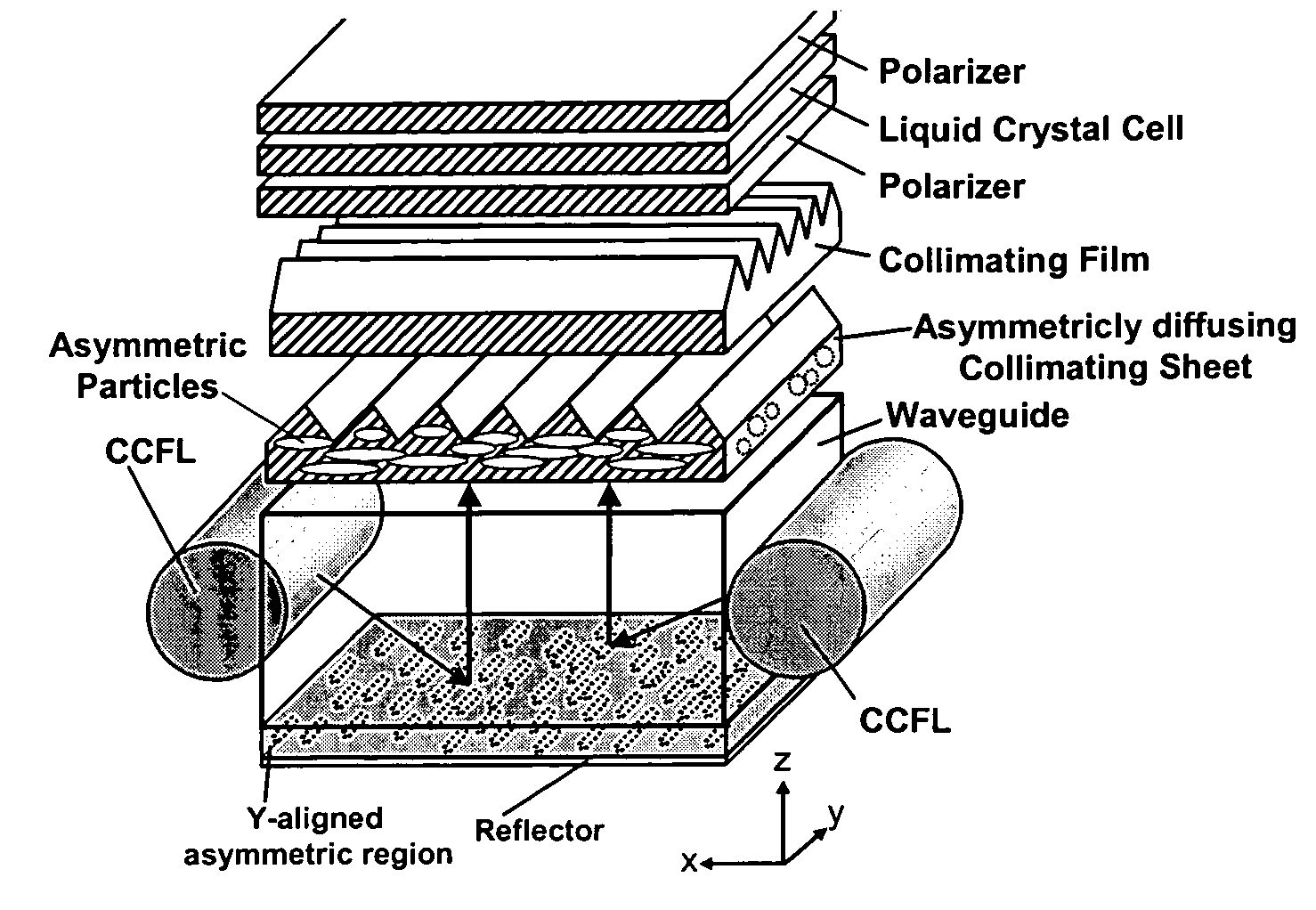
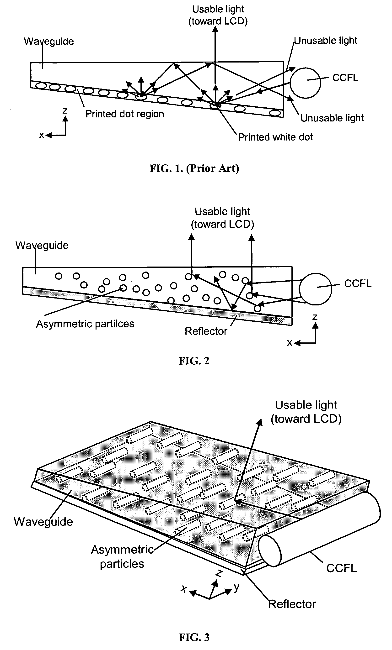
[0130] An enhanced LCD backlight, in accordance with the present invention, can be produced as described in FIG. 3, that is designed to have increased optical efficiency and therefore increased brightness relative to existing backlights. This is possible because the volumetric asymmetric diffusive region within the light guide allows for better control over the light scattering. Light from two CCFL lamps is coupled into the light guide. The light guide contains light scattering particles in a host matrix material. The particle chosen may be a polystyrene bead of diameter 5 μm dispersed at concentrations up to 10% by volume in a host matrix of acrylic. Other choices of particles and host matrix may provide equivalent performance. Asymmetry and alignment of the asymmetry can be created by stretching or extrusion processes. The asymmetrically diffusing light guide can be created by extruding, casting or coating, the mixture containing the particles. The light guide may be 2.5 mm in thi...

example 2

[0131] An enhanced LCD backlight, in accordance with the present invention, can be produced as described in FIG. 11, that is designed to have increased optical efficiency and therefore increased brightness relative to existing backlights. This is possible because the volumetric asymmetric diffusive region below the light guide allows for better control over the light scattering. Two crossed asymmetric light scattering regions are optically coupled to the non-scattering light guide. Light from two CCFL lamps is coupled into the light guide. The asymmetric light scattering regions contain asymmetric particles in a host matrix material. The regions may be created by creating a mixture consisting of polystyrene bead particles of diameter 5 μm dispersed at concentrations up to 10% by volume in a host matrix of acrylic. Other choices of particles and host matrix may provide equivalent performance. The asymmetrically diffusing regions can be created by extruding, casting or coating, the mi...

example 3

[0132] An enhanced LCD backlight, in accordance with the present invention, can be produced as described in FIG. 8, that is designed to have increased optical efficiency and therefore increased brightness relative to existing backlights. This is possible because the volumetric asymmetric diffusive region within the light guide allows for better control over the light scattering. Light from more than one side-emitting RGB LEDs coupled into the light guide through holes in the light guide. The light guide contains asymmetric light scattering particles aligned parallel to the line of LEDs. The asymmetric light scattering light guide contain asymmetric particles in a host matrix material. The regions may be created by creating a mixture consisting of polystyrene bead particles of diameter 5 μm dispersed at concentrations up to 10% by volume in a host matrix of acrylic. Other choices of particles and host matrix may provide equivalent performance. The asymmetrically diffusing light guide...


PUM


Abstract

The present invention provides an improved light guide with inherently more flexibility for display system designers and higher optical efficiency. By using a light guide containing substantially aligned non-spherical particles, more efficient control of the light scattering can be achieved. One or more regions containing ellipsoidal particles may be used and the particle sizes may vary between 2 and 100 microns in the smaller dimension. The light scattering regions may be substantially orthogonal in their axis of alignment. Alternatively, one or more asymmetrically scattering films can be used in combination with a backlight light guide and a reflector to produce an efficient backlight system. The light guides may be manufactured by embossing, stamping, or compression molding a light guide in a suitable light guide material containing asymmetric particles substantially aligned in one direction. The light scattering light guide or non-scattering light guide may be used with one or more light sources, collimating films or symmetric or asymmetric scattering films to produce an efficient backlight that can be combined with a liquid crystal display or other transmissive display. By maintaining more control over the scattering, the efficiency of the recycling of light by using reflective polarizers can also be increased.

Description

RELATED APPLICATIONS [0001] This application claims the benefit of priority under 35 U.S.C. 119(e) to copending U.S. Provisional Application Nos. 60 / 608,233, filed on Sep. 9, 2004, the entire contents of which is incorporated herein by reference. Related applications are Ser. No. 11 / 197,246 and 11 / 200,592, the entire contents of which are incorporated herein by reference.FIELD OF THE INVENTION [0002] The invention generally relates to an enhanced backlight and method of manufacture and more specifically its use as an LCD backlight. BACKGROUND OF THE INVENTION [0003] Conventional LCD backlighting assemblies use a linear cold cathode fluorescent lamp (CCFL) to inject light into the edge of a clear light guide. In order to extract light from the light guides in backlights, diffusing white spots are often printed on the bottom of the light guide. These spots reflectively diffuse light out of the light guide. The control over the angular spread of the reflected light from the dots is ver...

Claims


Application Information

Patent Timeline
IPC IPC(8): F21V9/14F21V7/04
CPCG02B6/0038G02B6/0041G02B6/0046G02B6/0051G02B6/0078G02B6/0055G02B6/0056G02B6/0065G02B6/0053
Inventor YEO, TERENCE E.COLEMAN, ZANE A.
Owner MASSACHUSETTS DEV FINANCE AGENCY
Why Eureka
Try Eureka