System for and method of extending vertical field of view in head up display utilizing a waveguide combiner

a combiner and vertical field technology, applied in the field of displays, can solve the problems of limiting the field of view and spectral range of the system, affecting the design of the system,

Active Publication Date: 2014-12-02
ROCKWELL COLLINS INC
View PDF109 Cites 161 Cited by
  • Summary
  • Abstract
  • Description
  • Claims
  • Application Information

AI Technical Summary

Problems solved by technology

Conventional HUDs are generally large, expensive and difficult to fit into small airplanes.
However, such systems have faced difficulties in design.
Diffraction gratings fabricated using embossing and casting processes are more repeatable but can be...

Method used


Image

  • System for and method of extending vertical field of view in head up display utilizing a waveguide combiner
  • System for and method of extending vertical field of view in head up display utilizing a waveguide combiner
  • System for and method of extending vertical field of view in head up display utilizing a waveguide combiner

Examples


Embodiment Construction

[0021]Before describing in detail the particular improved system and method, it should be observed that the invention includes, but is not limited to, a novel structural combination of optical components and not in the particular detailed configurations thereof. Accordingly, the structure, methods, functions, control and arrangement of components have been illustrated in the drawings by readily understandable block representations and schematic drawings, in order not to obscure the disclosure with structural details which will be readily apparent to those skilled in the art, having the benefit of the description herein. Further, the invention is not limited to the particular embodiments depicted in the exemplary diagrams, but should be construed in accordance with the language in the claims.

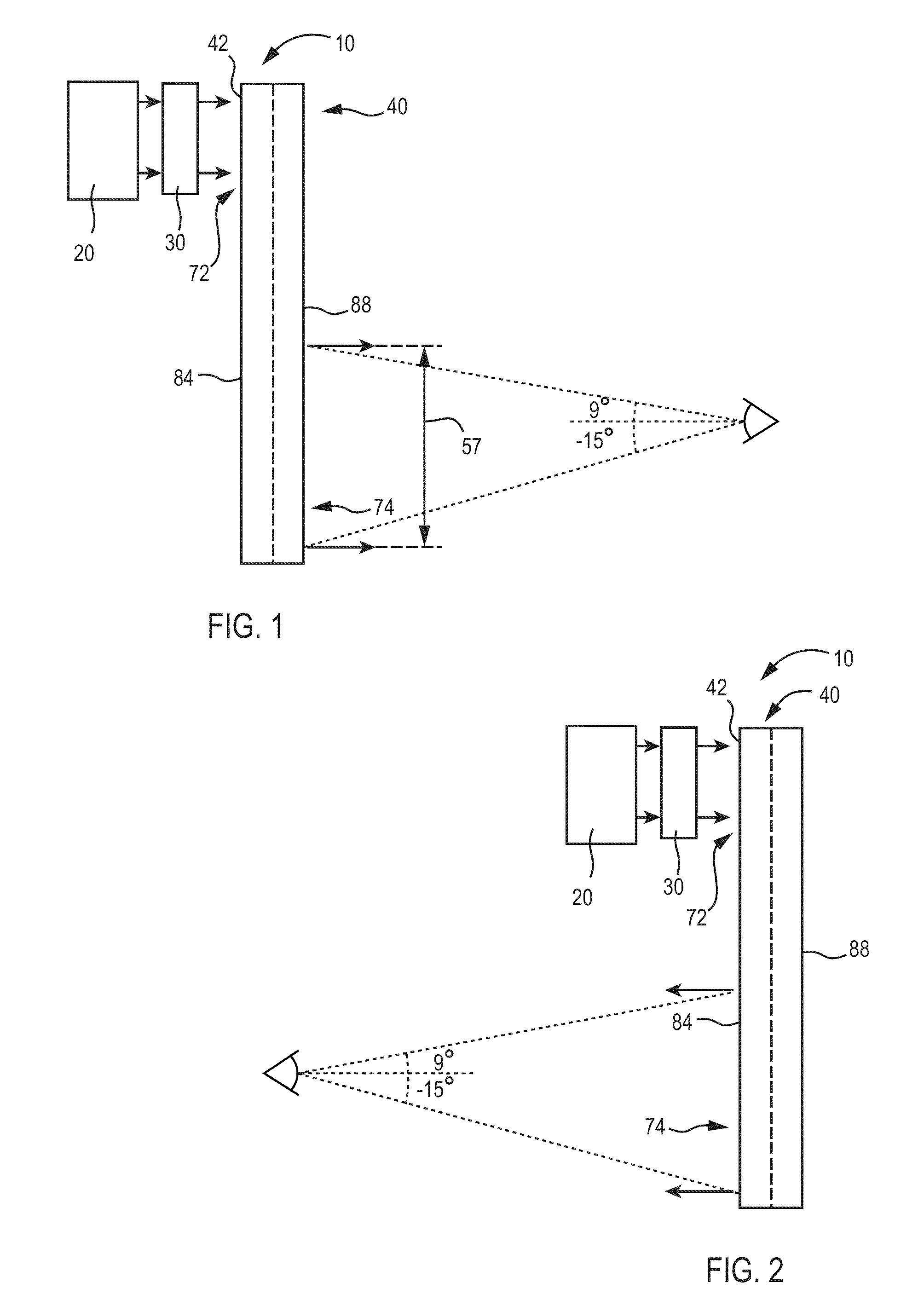
[0022]With reference to FIG. 1, head up display (HUD) system 10 can be utilized in various applications, including aviation, medical, naval, targeting, ground based, military, etc. HUD system 10 ...


PUM


Abstract

A Head Up Display can be utilized to find light from an energy source. The Head Up Display includes a first waveguide having a first input coupler and a first output coupler. The Head Up Display can also include a second waveguide having a second input coupler and a second output coupler. The first waveguide has a first major surface and the second waveguide has a second major surface, which are disposed approximately parallel to each other. The first waveguide and the second waveguide are positioned as a combiner and allowing viewing an outside feed and information from an image source. The first input coupler diffracts light in the first field of view into the first waveguide and light in a second field of view reaches the second input coupler and is diffracted into the second waveguide.

Description

CROSS REFERENCE TO RELATED APPLICATIONS[0001]The present application is related to: U.S. patent application Ser. No. 13 / 250,940, entitled, “Head Up Display (HUD) Utilizing Diffractive Gratings Having Graded Efficiency,” filed on an even date herewith, incorporated herein by reference, and assigned to the assignee of the present application; U.S. patent application Ser. No. 13 / 250,858, entitled, “Ultra-Compact HUD Utilizing Waveguide Pupil Expander With Surface Relief Gratings In High Refractive Index Materials,” filed on an even date herewith, incorporated herein by reference in its entirety, and assigned to the assignee of the present application; U.S. patent application Ser. No. 13 / 250,970, entitled, “System for and Method of Stowing HUD Combiners,” filed on an even date herewith, incorporated herein by reference in its entirety, and assigned to the assignee of the present application; U.S. patent application Ser. No. 13 / 250,994, entitled, “Compact Head Up Display (HUD) for Cockpi...

Claims


Application Information

Patent Timeline
IPC IPC(8): G02B6/26G02B27/14
CPCG02B27/0103G02B2027/0118G02B2027/0125
Inventor BROWN, ROBERT D.STAHL, KURT A.WOOD, ROBERT B.
Owner ROCKWELL COLLINS INC
Why Eureka
Try Eureka