Method for dispersion compensation in a mesh optical network, and a network using same

a technology of optical network and mesh, applied in multiplex communication, electrical apparatus, wavelength-division multiplex systems, etc., can solve problems such as non-minimizing and serious problems such as dispersion mapping

Active Publication Date: 2014-12-09
ECE TELECOM LTD
View PDF2 Cites 0 Cited by
  • Summary
  • Abstract
  • Description
  • Claims
  • Application Information

AI Technical Summary

Benefits of technology

[0014]Surprisingly, in view of all the problems noticed above, there exists quite a simple solution which has been found by the Inventor. The advantage of this solution that it does not need to know the trails in advance—it only needs to know possible termination points (say, ADD and Drop points) of traffic trails in the mesh network.
[0016]It is known to those skilled in the art, that different bit rates of traffic raise different requirements to chromatic dispersion in the trail used by the traffic, and in particular—different requirements to minimizing nonlinear impairments.
[0018]However, nobody tried to address the most practical task of performing dispersion mapping in an optical mesh network which is simultaneously utilized by services having different bit rates. Moreover, nobody simultaneously tried to resolve the problem of minimizing non-linear impairment by dispersion mapping in mesh networks.
[0038]Since, according to the method, RDS per span is selected to be positive and less than about 3 km, the requirement to 10 G trails (total RDS<80 km) is fulfilled in practice. Usually, when a trail comprises up to 20 spans (which is normal in practice), the requirement is easily satisfied.

Problems solved by technology

Dispersion mapping which would allow minimizing non-linear impairments seems problematic in mesh networks, since trails of traffic services in the mesh usually overlap one another, may start and terminate at any node of the network, and since any span may be the first span of one trail, and simultaneously the last span of another trail in the mesh network.
In mesh networks, where trails practically cannot be predicted and pre-counted in advance, dispersion mapping turns to be a serious problem, especially in case when different bit rates are used in the network.

Method used


Image

  • Method for dispersion compensation in a mesh optical network, and a network using same
  • Method for dispersion compensation in a mesh optical network, and a network using same
  • Method for dispersion compensation in a mesh optical network, and a network using same

Examples


Embodiment Construction

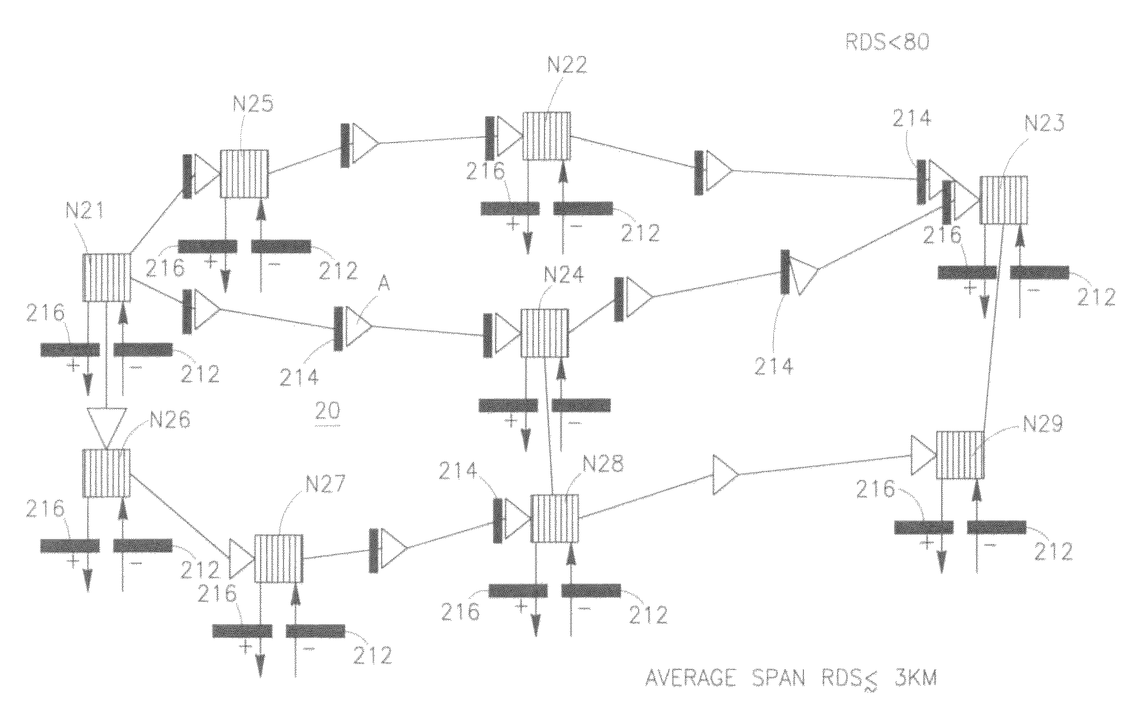
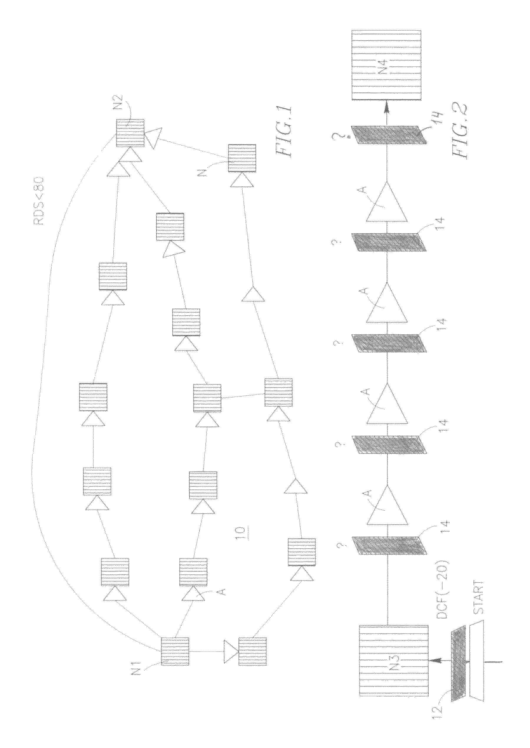
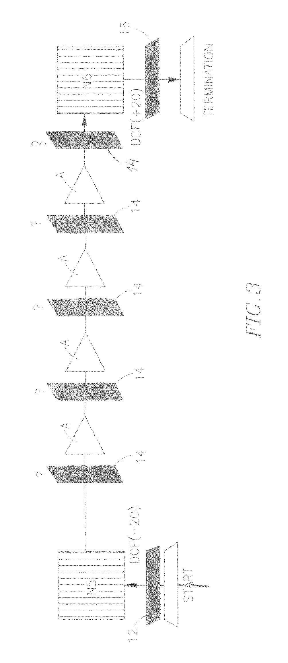
[0073]FIG. 1 shows an optical mesh network 10 comprising a plurality of nodes schematically illustrated by hatched boxes N (N1, N2 . . . ). The nodes are interconnected by links, each equipped by at least one optical amplifier (schematically shown by triangles A). Trails of traffic services may be formed between each two nodes of the network. It is accepted in practice that for traffic services having bit rate 10 GB / s, a trail (say, the trail between N1 and N2) should have a positive total (trail) residual dispersion RDS being lower than 80 km. The total RDS1-N2 (see a solid thick line) is schematically marked in the drawing near the line.

[0074]There is another (second) practical requirement for traffic of 10 Gbps, which has been noticed by the Inventor. The RSD of the last span of the trail should be greater than of about +20 km. But now let us look at the drawing and ask: “which span in the mesh network can be considered to be the last span?” or practically “which span should be p...


PUM


Abstract

A method is provided for carrying out dispersion compensation in an optical mesh network supporting simultaneously traffic services being provided at two or three different bit rates including a basic bit rate being 10 Gbps and at least one higher bit rate selected from among 40 Gbps and 100 Gbps. The method comprises the following steps: providing in-line dispersion compensation for every span in the network so as to reach positive average residual dispersion RDS per span extending to less than about 3 km; providing start points of possible trails in the network with respective external, pre-compensation negative Dispersion Compensation modules (DCMs), and providing termination points of possible trails in the network with respective external post-compensation positive DCMs.

Description

CROSS-REFERENCE TO RELATED APPLICATIONS[0001]This application claims priority of Israel Patent Application No. 214875, filed Aug. 29, 2011, the disclosure of which is incorporated by reference herein in its entirety.FIELD OF THE INVENTION[0002]The present invention relates to a technology for designing an optical mesh network to balance chromatic dispersion in it and to minimize non-linearity impairments in the network, and to the resulting mesh network where the dispersion is balanced / compensated.BACKGROUND OF THE INVENTION[0003]Various methods of mapping dispersion in optical networks are known in the art.[0004]US2010329695A relates to dispersion slope compensation and dispersion map management systems and methods in an optical network utilizing a reconfigurable optical add-drop multiplexer (ROADM) with a plurality of different values of dispersion compensation modules (DCMs). The DCMs form a dispersion compensation ladder at certain intermediate nodes in the optical network to pr...

Claims


Application Information

Patent Timeline
Patent Type & Authority Patents(United States)
IPC IPC(8): H04B10/2525H04J14/02H04B10/00
CPCH04B10/25253
Inventor LICHTMAN, EYAL
Owner ECE TELECOM LTD
Why Eureka
Try Eureka