
Methods, systems, and articles of manufacture for generating multi-layer local maximal orthogonal routing paths in fractured space

a technology of fractured space, which is applied in the field of methods, systems and articles of manufacture for generating multi-layer local maximal orthogonal routing paths in fractured space. it can solve the problems of routing failure and customer use restrictive routing rules

Active Publication Date: 2014-12-09
CADENCE DESIGN SYST INC
View PDF4 Cites 0 Cited by
  • Summary
  • Abstract
  • Description
  • Claims
  • Application Information

AI Technical Summary

Benefits of technology

The patent text describes a method or system for designing electronic circuits that allows for the placement of components without bending the lines that connect them. This is important for preserving the proper order of components and ensuring proper functionality. The system uses a technique called blocked modeling to make these placements while maintaining the relative order of components. This can be useful for designing complex electronic circuits that require precise component placement.

Problems solved by technology

That is, a router fails when two pins on the same net that should be connected are open, when two pins on two different nets that should remain open are shorted, or when some design rules are violated during routing.
In modern integrated circuits, complex routing rules have led some customers to use restrictive routing rules.
Nonetheless, a subsequent addition to or modification of an electronic circuit design may lead to a certain feature encroaching upon a space claimed by another circuit feature such as an interconnect segment and thus requires the latter to be modified, often resulting in multiple bends to free up the space encroached upon to accommodate the addition to or modification of the electronic circuit design.

Method used


Image

  • Methods, systems, and articles of manufacture for generating multi-layer local maximal orthogonal routing paths in fractured space
  • Methods, systems, and articles of manufacture for generating multi-layer local maximal orthogonal routing paths in fractured space
  • Methods, systems, and articles of manufacture for generating multi-layer local maximal orthogonal routing paths in fractured space

Examples


Embodiment Construction

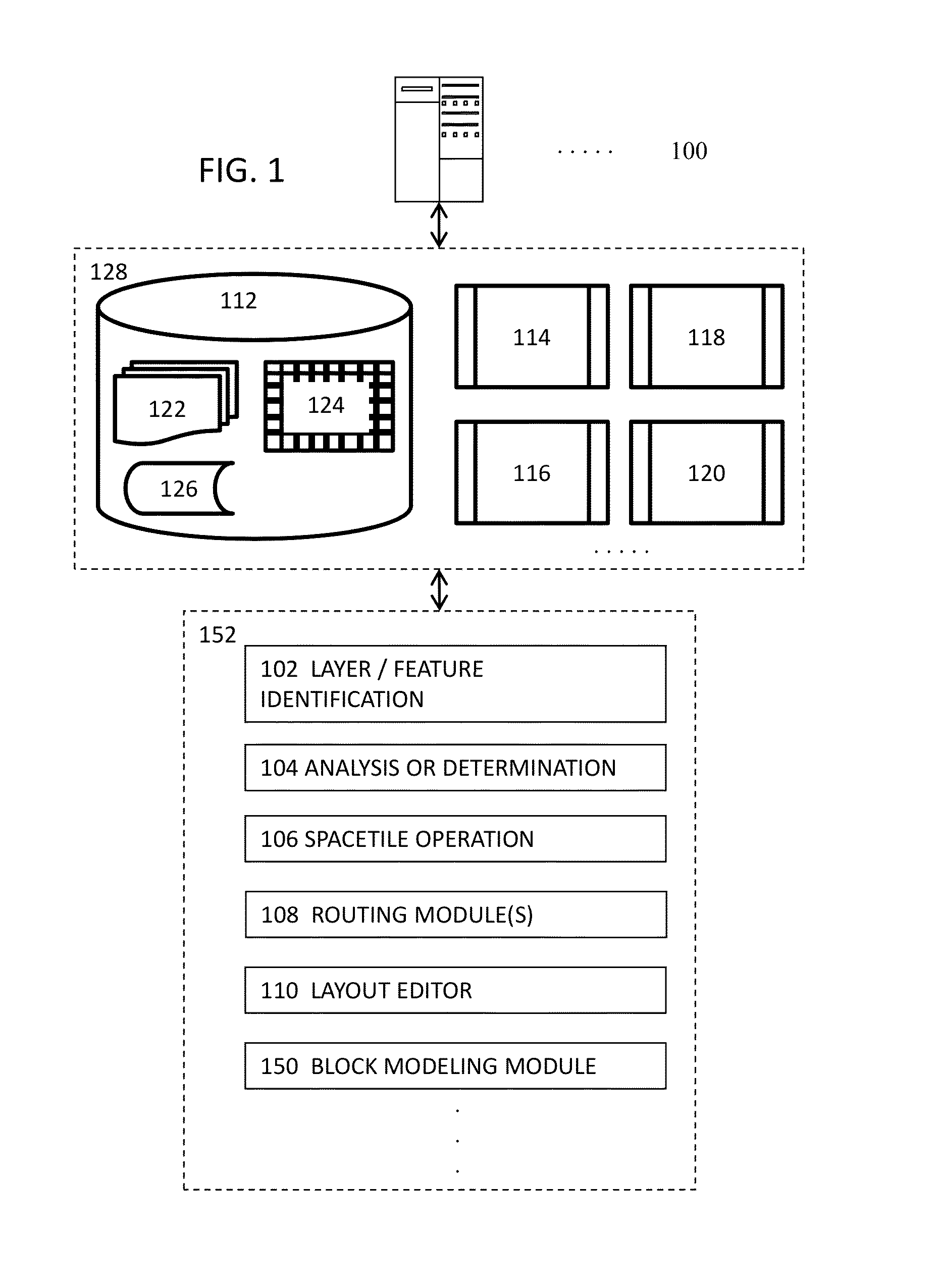
[0046]Various embodiments of the invention are directed to a methods, systems, and articles of manufacture for implementing multi-layer local maximal routing paths. Other objects, features, and advantages of the invention are described in the detailed description, figures, and claims.

[0047]Various embodiments will now be described in detail with reference to the drawings, which are provided as illustrative examples of the invention so as to enable those skilled in the art to practice the invention. Notably, the figures and the examples below are not meant to limit the scope of the present invention. Where certain elements of the present invention may be partially or fully implemented using known components (or methods or processes), only those portions of such known components (or methods or processes) that are necessary for an understanding of the present invention will be described, and the detailed descriptions of other portions of such known components (or methods or processes) ...


PUM


Abstract

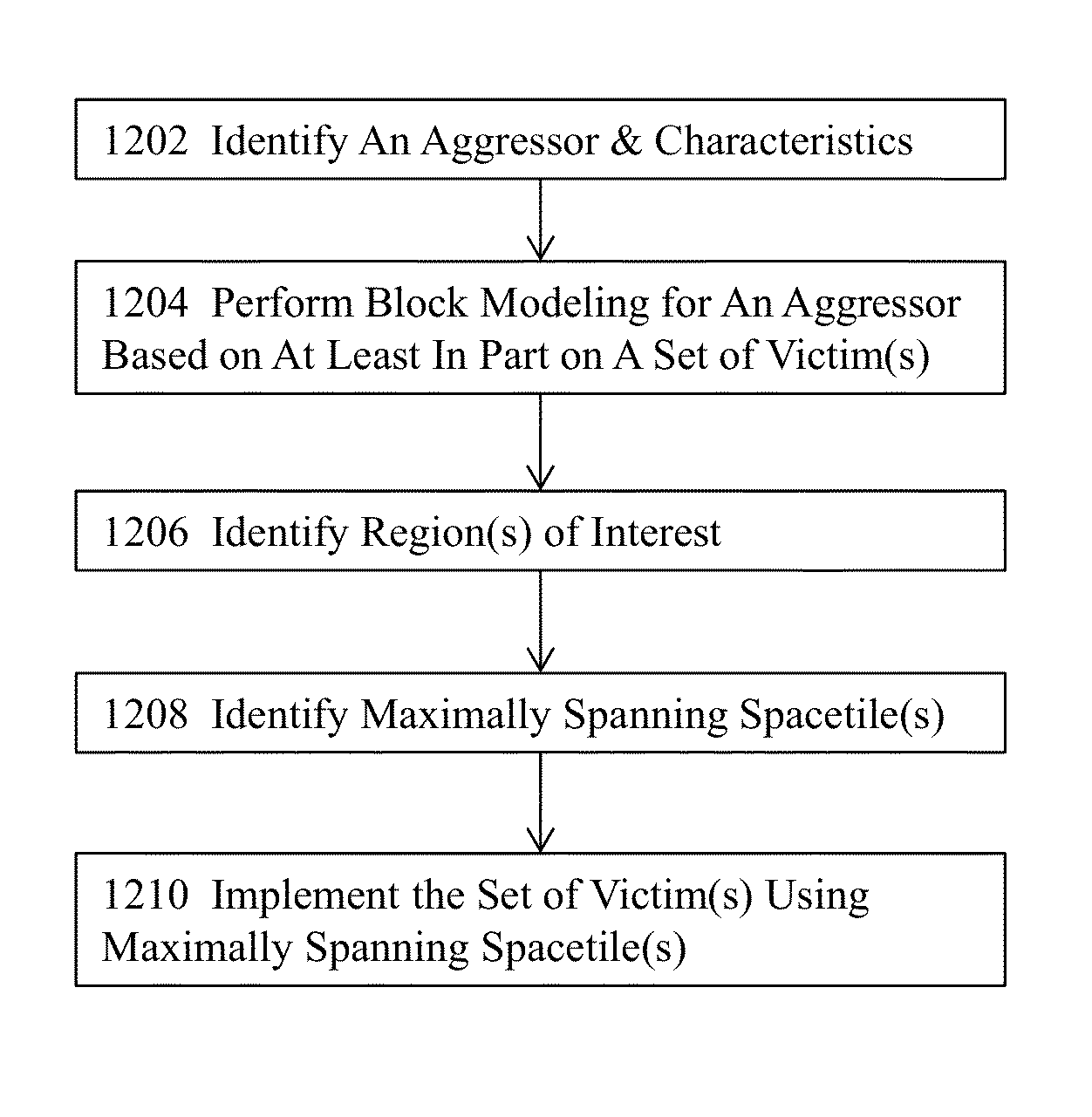
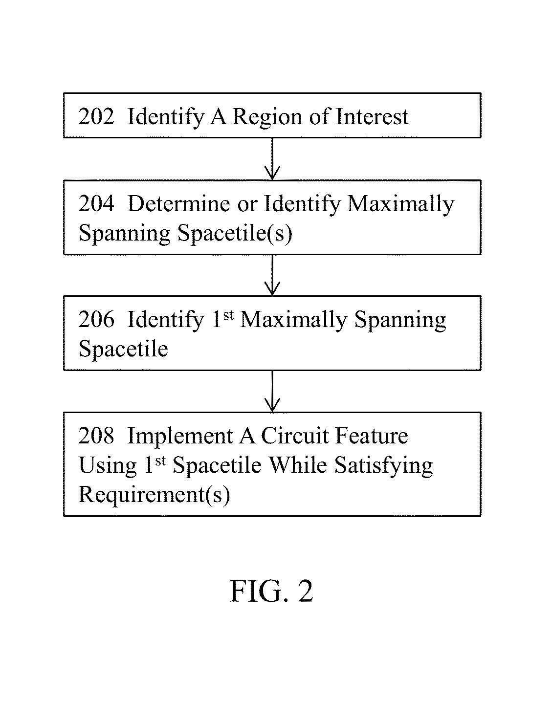
Various embodiments identify a design including circuit features and identify an operation that produces an aggressor for victim(s). The operation on the aggressor and the set of victims are implemented using local maximally spanning spacetile(s) while satisfying some design requirements. Where the set of victims includes interconnects, the design may allow no bend in some interconnects. One or more spacetiles are used to perform the operation on the aggressor and implement the interconnects while introducing no bends in the interconnects by using local maximally spanning spacetile(s). Some implementation may perform block modeling for the aggressor to perform the operation on the aggressor and implement a set of victims while preserving the relative order of the interconnects by using the block modeling for the aggressor.

Description

CROSS REFERENCE TO RELATED APPLICATION(S)[0001]This application is a continuation of U.S. patent application Ser. No. 13 / 692,970, filed concurrently with the current application on Dec. 3, 2012 and entitled “METHODS, SYSTEMS, AND ARTICLES OF MANUFACTURE FOR GENERATING MULTI-LAYER LOCAL MAXIMAL ORTHOGONAL ROUTING PATHS IN FRACTURED SPACE”. The content of the application is hereby incorporated by reference in its entirety for all purposes.BACKGROUND[0002]Integrated circuits, or ICs, are created by patterning a substrate and materials deposited on the substrate. The substrate is typically a semiconductor wafer. The patterned features make up devices and interconnections. This process generally starts with a designer creating an integrated circuit by hierarchically defining functional components of the circuit using a hardware description language. From this high-level functional description, a physical circuit implementation dataset is created, which is usually in the form of a netlist...

Claims


Application Information

Patent Timeline
Patent Type & Authority Patents(United States)
IPC IPC(8): G06F17/50
CPCG06F17/5077G06F30/367G06F30/394G06F2119/10
Inventor RAJ, SATISHANANTHRAM, SUPRIYA
Owner CADENCE DESIGN SYST INC
Learn More