Panel for a domestic appliance having a rotary switch, and domestic appliance

a technology of rotary switch and panel, which is applied in the field of panel, can solve the problems of large amount of expenditure, large amount of construction, and large amount of required components, and achieve the effect of low cost and low total depth

Inactive Publication Date: 2014-12-16
PAS DEUTLAND
View PDF18 Cites 3 Cited by
  • Summary
  • Abstract
  • Description
  • Claims
  • Application Information

AI Technical Summary

Benefits of technology

[0008]Therefore, one object of the present disclosure is to disclose a panel with an improved rotary switch which is preferably produced at low cost, can be matched to specific requirements in a simple manner and allows for a low total depth. A further object of the present disclosure is to disclose a corresponding improved domestic appliance having a rotary switch and / or having a panel.

Problems solved by technology

Rotary switches according to the prior art, as shown in DE 22 45 444 for example, are of relatively complex construction and can be matched to specific requirements only with a considerable amount of expenditure.
In addition, the required components are relatively expensive and have, overall, a relatively large total height or total depth.

Method used


Image

  • Panel for a domestic appliance having a rotary switch, and domestic appliance
  • Panel for a domestic appliance having a rotary switch, and domestic appliance
  • Panel for a domestic appliance having a rotary switch, and domestic appliance

Examples


first embodiment

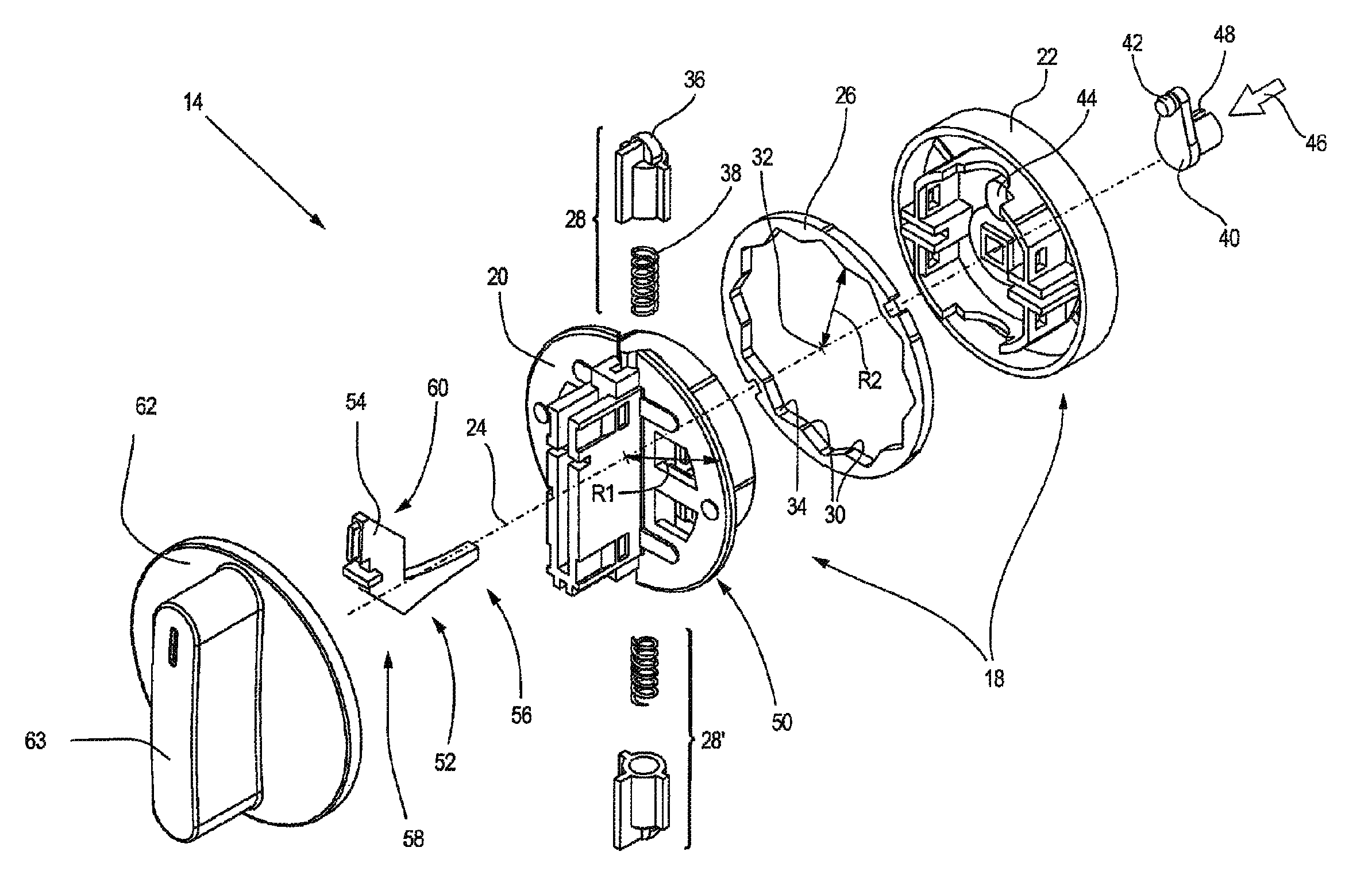
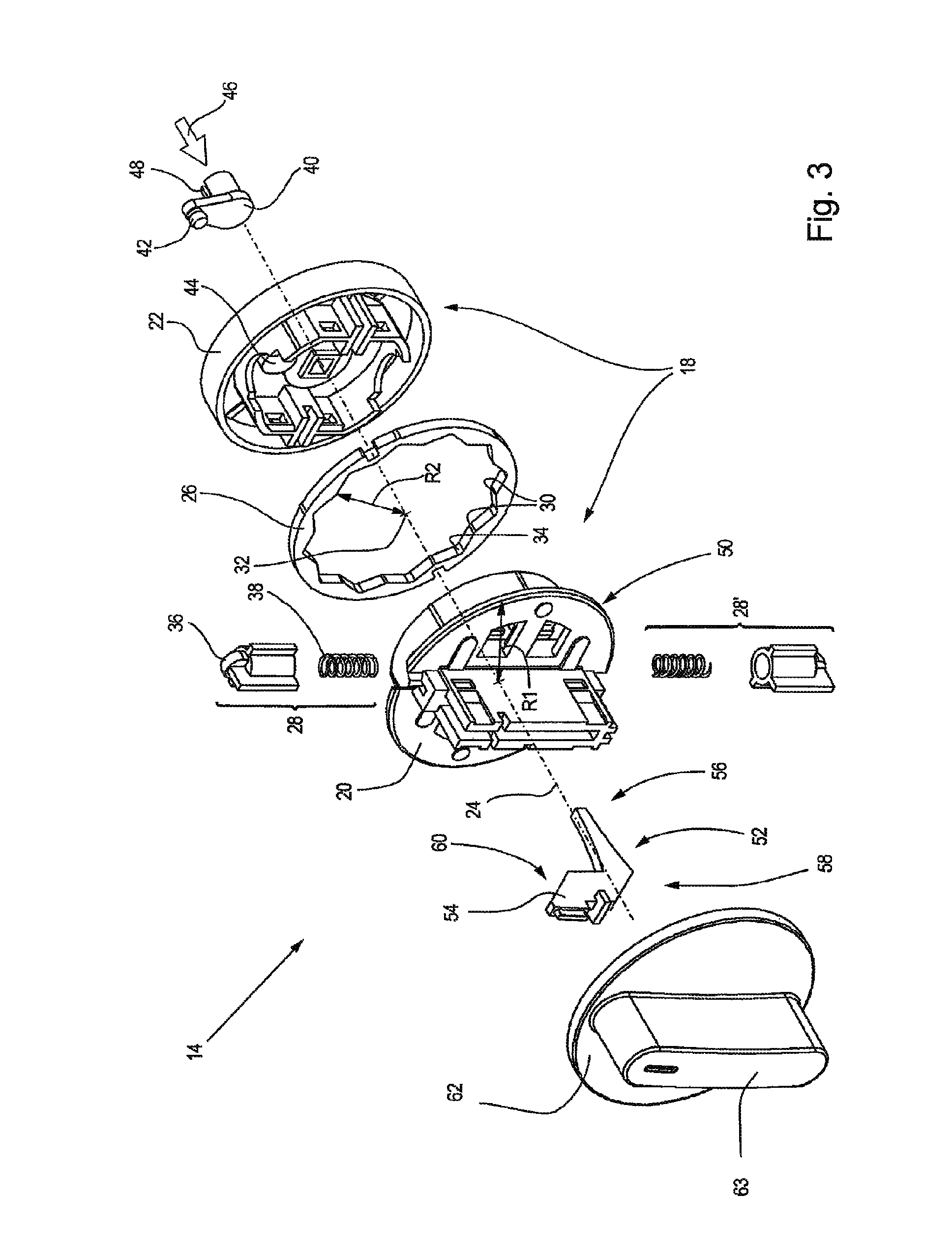
[0056]FIG. 3 shows a rotary switch 14, as it is inserted into the panel 10 according to FIG. 1. The rotary switch 14 has a rotary element 18 which has a first shaped part 20 and a second shaped part 22 in this case. The rotary element 18, and therefore also the first shaped part 20 and the second shaped part 22, are arranged along a rotation axis 24.

[0057]The rotary switch 14 also has a latching ring 26 which is likewise arranged along the rotary axis 24. The rotary switch 14 also has at least one latching element 28, in this case two latching elements 28, 28′. Whereas the rotary element 18 can rotate about the rotation axis 24, the latching ring 26 is seated in a rotationally fixed manner in relation to the rotation axis 24, that is to say it does not execute a rotary movement about the rotation axis 24, in the installed state. This means that the rotary element 18 rotates relative to the latching ring 26.

[0058]The latching ring 26 has at least one latching lug 30, in particular a ...

second embodiment

[0073]FIG. 9 shows an alternative embodiment of a latching element 28, 28′ according to a rotary switch 14. The latching head 36 here is designed in a similar manner to as has been explained with reference to FIG. 3. In order to prestress the latching head 36 radially outward, the spring element 38 is designed as a pair of spring bows in this case. The latching element 28, 28′ is integrally formed with its latching head 36 and the spring element 38.

[0074]In should be noted, in general, that all elements of the rotary switch 14 and, in particular, also the parts of the panel 10 can be produced from plastic. This simplifies production and reduces production costs. If an embodiment according to FIG. 3 is selected, it is advantageous to produce the spring elements 38 from metal.

[0075]Overall, an improved panel with a rotary switch has been disclosed, allowing to realize a rotary switch in a cost-effective manner and to be matched to specific requirements in a simple manner in said panel...


PUM


Abstract

A panel for a domestic appliance having a rotary switch, the rotary switch having a rotary element, a latching ring, at least one latching element and a rotation axis about which the rotary element rotates relative to the latching ring, wherein the latching ring has at least one latching lug on its inner face, said latching lug projecting radially toward the center the latching ring, wherein the latching element is held on the rotary element and is prestressed radially outward against the inner face of the latching ring, wherein the rotary element and the latching ring are arranged along the rotation axis, and wherein the latching ring is arranged in a rotationally fixed manner on the panel. A corresponding domestic appliance having a panel is also disclosed.

Description

CROSS REFERENCES TO RELATED APPLICATIONS[0001]This application is a continuation of international patent application PCT / EP2011 / 053123, filed on Mar. 2, 2011 designating the U.S., which international patent application has been published in German language and claims priority from German patent application DE 10 2010 009 993.7, filed on Mar. 2, 2010. The entire contents of these priority applications are incorporated herein by reference.BACKGROUND[0002]The present disclosure relates to a panel for a domestic appliance having a rotary switch.[0003]The disclosure also relates to a domestic appliance having a rotary switch and / or having a panel.[0004]Domestic appliances, including washing machines and dryers in particular, are generally operated using operator control elements which are arranged on the front face of the domestic appliance. The operator control elements are usually integrated in a panel in this case.[0005]Typical operator control elements include so-called rotary switch...

Claims


Application Information

Patent Timeline
Patent Type & Authority Patents(United States)
IPC IPC(8): G05G1/10H01H19/02B60K37/06H01H19/14G05G5/03H01H13/62H01H9/00
CPCB60K2350/102G05G1/10H01H19/14B60K37/06G05G1/105H01H19/025G05G5/03Y10T74/2084B60K2370/158B60K2370/126
Inventor KLIMECKI, MAREK
Owner PAS DEUTLAND
Why Eureka
Try Eureka