Active electronic tag apparatus for memory card

a technology of active electronic tag and memory card, which is applied in the direction of mechanical actuation of burglar alarms, instruments, electromagnetic radiation sensing, etc., can solve the problems that the information of the electronic tag cannot be effectively transmitted to the card reader, and the electronic tag dimension is difficult to be decreased, so as to achieve the effect of increasing the transmitting distance reducing the area of the active electronic tag

Inactive Publication Date: 2014-12-23
BEING TECH ELECTRONICS
View PDF3 Cites 0 Cited by
  • Summary
  • Abstract
  • Description
  • Claims
  • Application Information

AI Technical Summary

Benefits of technology

[0007]An aspect of the present invention is to provide an active electronic tag to effectively transmit information even if the antenna area of the electronic tag is reduced, and to be suitable for a memory card or a device of small space.
[0014]According to another embodiment of the present invention, the step of generating the positive carrier and the negative carrier includes generating the oscillator frequency; dividing the oscillator frequency to generate an internal clock; delaying the internal clock and generating a plurality of delay clocks by the delay circuit, wherein the plurality of delay clocks have identical frequencies equal to a frequency of the internal clock and different phases; selecting a delay clock with a phase closest or secondarily closest to a phase of the first carrier from the plurality of delay clocks as the positive carrier, wherein the positive carrier has a corresponding phase locking count; and selecting the negative carrier with a phase difference of 180 degrees comparing to the first carrier from the plurality of delay clocks according to the phase locking count to control the response signal carried on the negative carrier to cancel the first carrier on the card reader.
[0018]Besides, the phase synchronization locking circuit may rapidly generate the positive carrier with a phase identical to the first carrier and the negative carrier with a phase inverting to the first carrier. The positive carrier is utilized for stabilizing the driving clock of the decoding circuit, and the negative carrier may effectively cancel the first carrier by the response signal. By the above embodiment, the area of the active electronic tag may be reduced, and the transmitting distance of the active electronic tag may be increased, such that the application of the active electronic tag is more wide and suitable for the application of the memory card.

Problems solved by technology

Electronic products are required to be slim and light; however, the dimension of the electronic tag is difficult to be decreased due to the limitation of the antenna area of the electronic tag.
As a result, the load variation of the electronic tag is difficult to change the voltage of the card reader, and information of the electronic tag cannot be effectively transmitted to the card reader.

Method used


Image

  • Active electronic tag apparatus for memory card
  • Active electronic tag apparatus for memory card
  • Active electronic tag apparatus for memory card

Examples


Embodiment Construction

[0024]In order to make the description of the present invention more detail and complete, the figures and the following various embodiments may be referenced, and the components with the same number in the figures represent the same or similar components. On the other hand, the well-known components and steps are not described in the embodiments to avoid resulting in unnecessary limitations to the present invention.

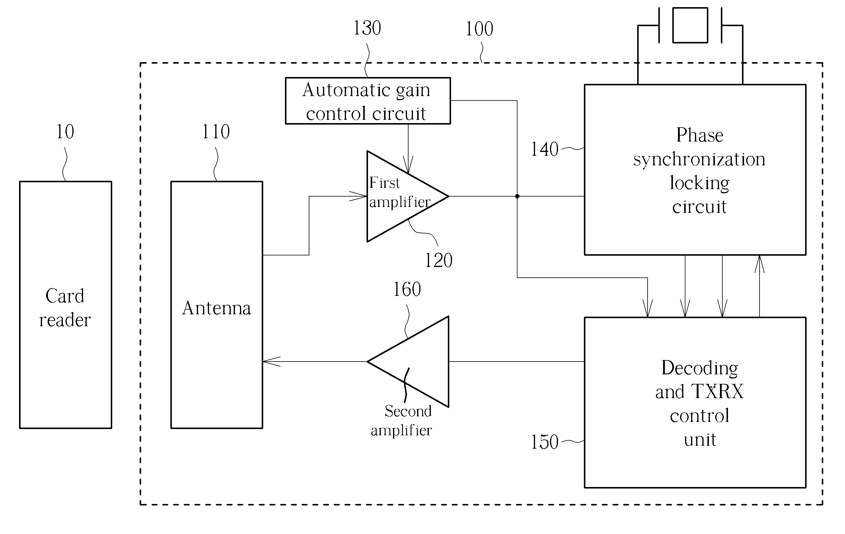
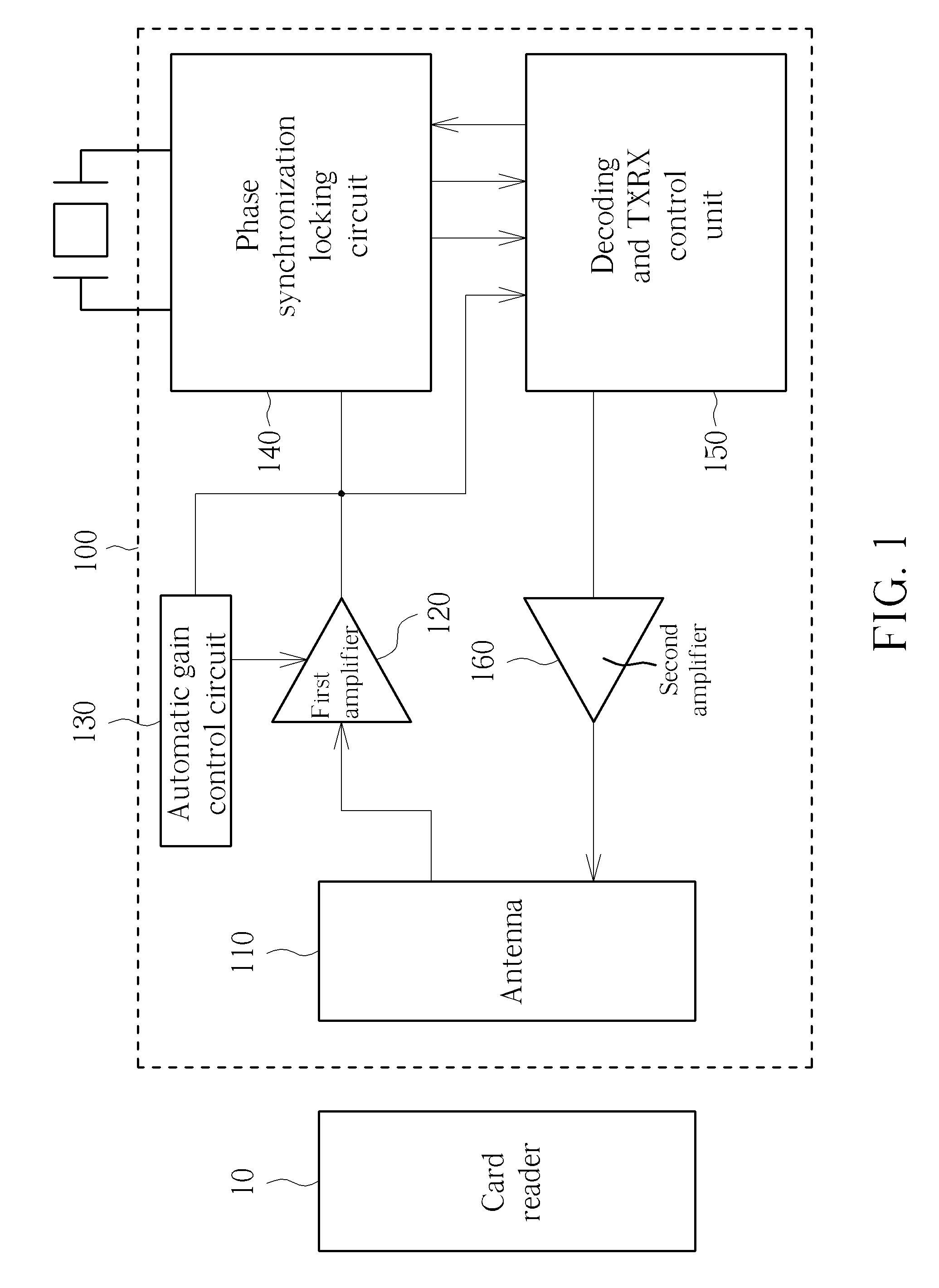
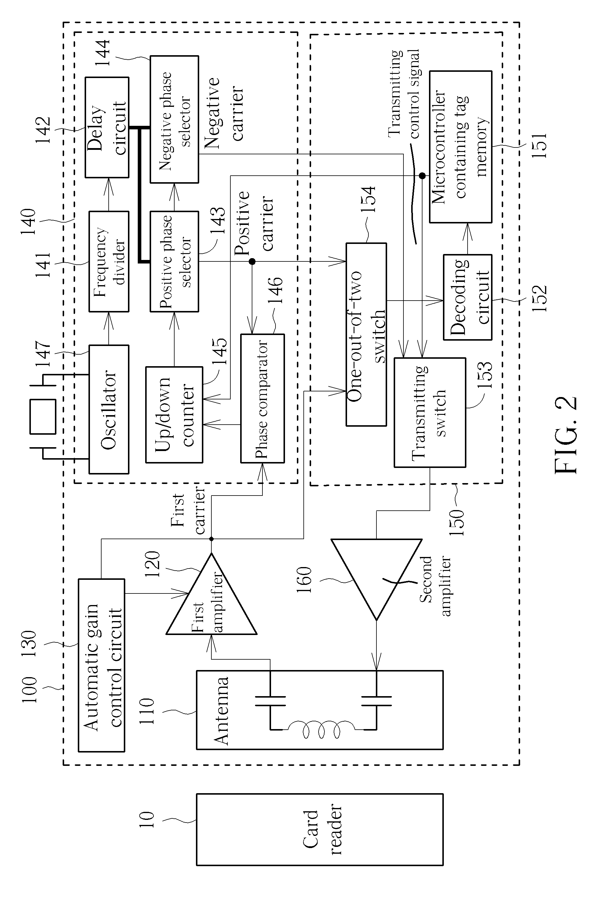
[0025]An active electronic tag provided by an embodiment of the present invention is utilized for solving the problem that the information of the active electronic tag may not be effectively transmitted when dimension or area of an antenna is reduced. Since the active electronic tag cancels a carrier on a card reader by transmitting a response signal to the card reader, when the dimension or area of the antenna is reduced, the response signal may be enhanced through an amplifier.

[0026]Additionally, in order to utilize the response signal to cancel the carrier on the card ...


PUM


Abstract

An active electronic tag for a memory card is disclosed herein. The active electronic tag includes an antenna, a first amplifier, an automatic gain control circuit, a phase synchronization locking circuit, a decoding and TX / RX control unit and a second amplifier. The antenna receives a detecting signal transmitted from a card reader, in which the detecting signal is carried on a first carrier. The phase synchronization locking circuit generates a positive carrier and a negative carrier with a phase difference of 180 degree. The decoding and TX / RX control unit generates a response signal, which is carried on the negative carrier. By utilizing the phase difference of the first carrier and the negative carrier, the response signal cancels the first carrier on the card reader, so as to transmit the information saved inside the active electronic tag.

Description

BACKGROUND OF THE INVENTION[0001]1. Field of the Invention[0002]The present invention relates to an active electronic tag apparatus for a memory card and includes a structure and related modulation method of the active electronic tag apparatus.[0003]2. Description of the Prior Art[0004]With the development of wireless technology, an electronic tag, which includes a radio frequency circuit and is utilized for storing information, has been widely used, such as identification, an access control system or electronic money. A typical electronic tag is passive, which receives a detecting signal and a carrier transmitted from a card reader as a power source, and utilizes a coupling effect between antennas to change a voltage of the card reader by a load variation of the electronic tag, so as to transmit information.[0005]Electronic products are required to be slim and light; however, the dimension of the electronic tag is difficult to be decreased due to the limitation of the antenna area ...

Claims


Application Information

Patent Timeline
Patent Type & Authority Patents(United States)
IPC IPC(8): G06K19/07H04Q5/22G06K7/10
CPCG06K7/10009G06K19/0723G06K19/073H03G3/3052H04B5/0031H04B5/0056
Inventor KU, CHIUNG-CHING
Owner BEING TECH ELECTRONICS
Why Eureka
Try Eureka