
Method and apparatus for detecting branch fibers, and passive optical network

a passive optical network and branch fiber technology, applied in the field of passive optical network technologies, can solve the problems of increasing the difficulty of implementation, the test device cannot distinguish the specific branch fiber from which each test signal is received, and the general lack of information of signals, etc., to achieve simple implementation of branch fiber detection, low cost, and convenient.

Active Publication Date: 2014-12-23
HUAWEI TECH CO LTD
View PDF21 Cites 6 Cited by
  • Summary
  • Abstract
  • Description
  • Claims
  • Application Information

AI Technical Summary

Benefits of technology

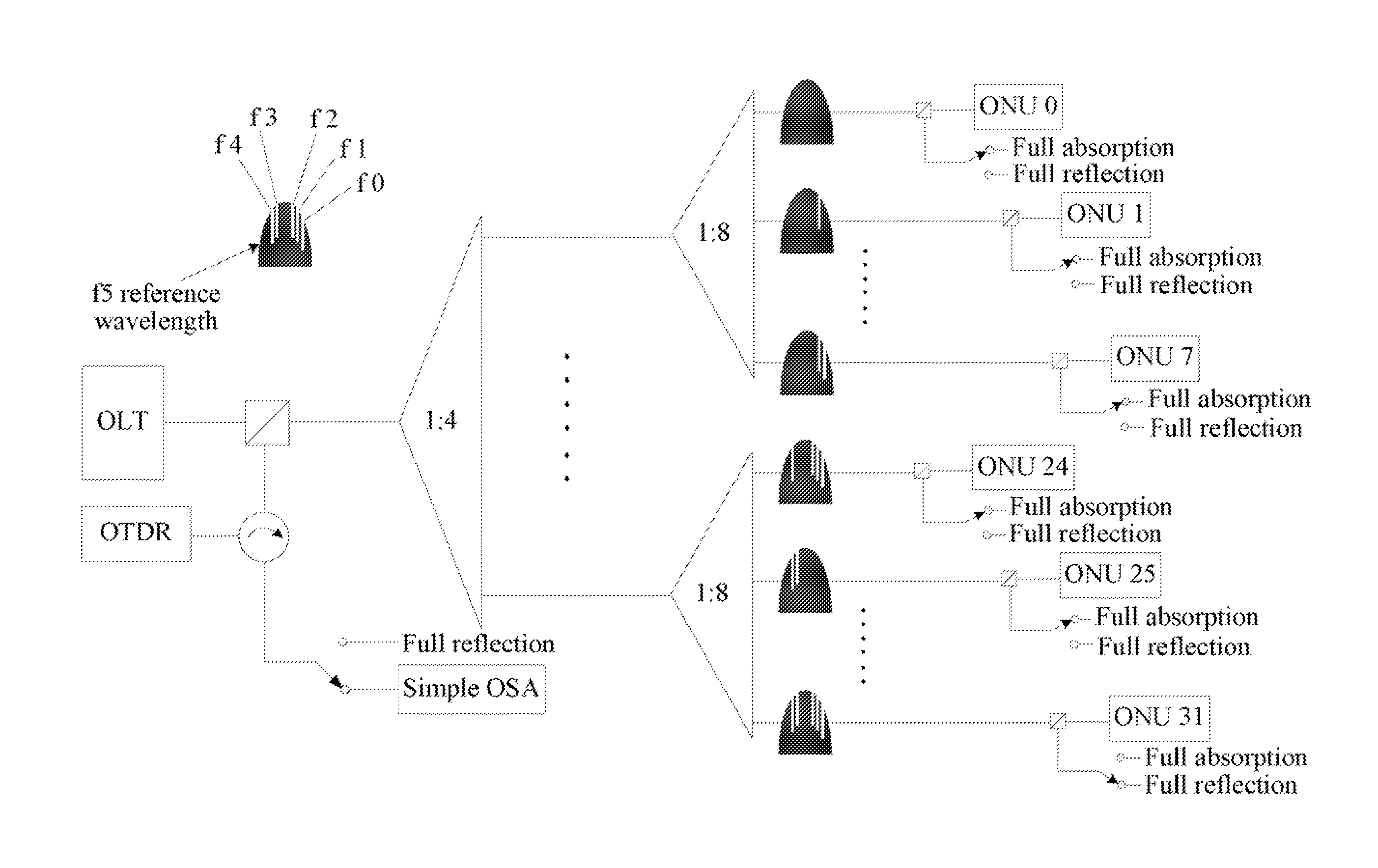
[0012]In the technical solutions of the present disclosure, the identification information corresponding to each branch fiber is added into a corresponding test signal at a port of the optical splitting module, so that the reflection signal of the test signal reflected from an end of the detected branch fiber is added with the identification information of the detected branch fiber. Therefore, the test device in the central office can directly identify the detected branch fiber corresponding to the reflection signal, and obtain the channel characteristics of the detected branch fiber according to the reflection signal. In this way, in the technical solutions of the present disclosure, the branch fibers do not necessarily have different lengths, and do not necessarily use different test wavelengths; instead, a normal test device can be used to detect the branch fibers. Therefore, the implementation of detection of the branch fibers is simple, convenient, and has a low cost.

Problems solved by technology

However, the test signals generally do not carry information for identifying the corresponding branch fiber.
Therefore, after receiving the multiple test signals, the test device cannot distinguish the specific branch fiber from which each test signal comes.
However, this method for identifying the test signal requires that branch fibers to have different lengths at the time of network constructing the PON, which increases the difficulty of implementation.
However, since the test signals are normally provided by the test device in the central office, in order to send the test signals with different wavelengths, this method has a high requirement on a tunable laser in the test device such as an OTDR (Optical Time Domain Reflectometer) in the central office, thus a cost for implementing this method is high.

Method used


Image

  • Method and apparatus for detecting branch fibers, and passive optical network
  • Method and apparatus for detecting branch fibers, and passive optical network
  • Method and apparatus for detecting branch fibers, and passive optical network

Examples


embodiment 1

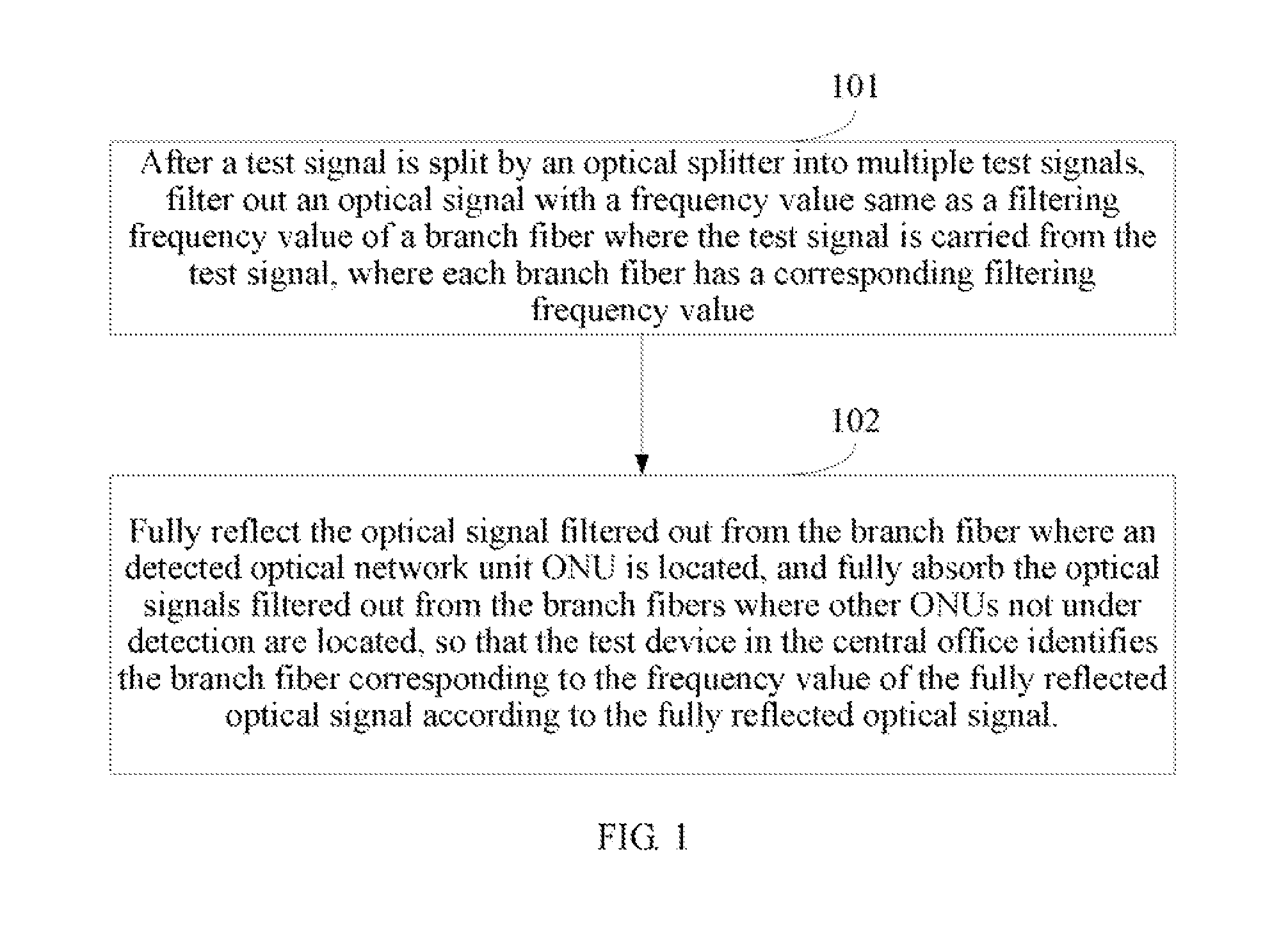
[0026]FIG. 1 is a flowchart of a method for detecting branch fibers according to an embodiment of the present disclosure. The method includes the following steps.

[0027]Step 101: After a test signal is split by an optical splitter into multiple test signals, filter out an optical signal with a frequency value same as a filtering frequency value of a branch fiber where the test signal is carried from the test signal, where each branch fiber has a corresponding filtering frequency value.

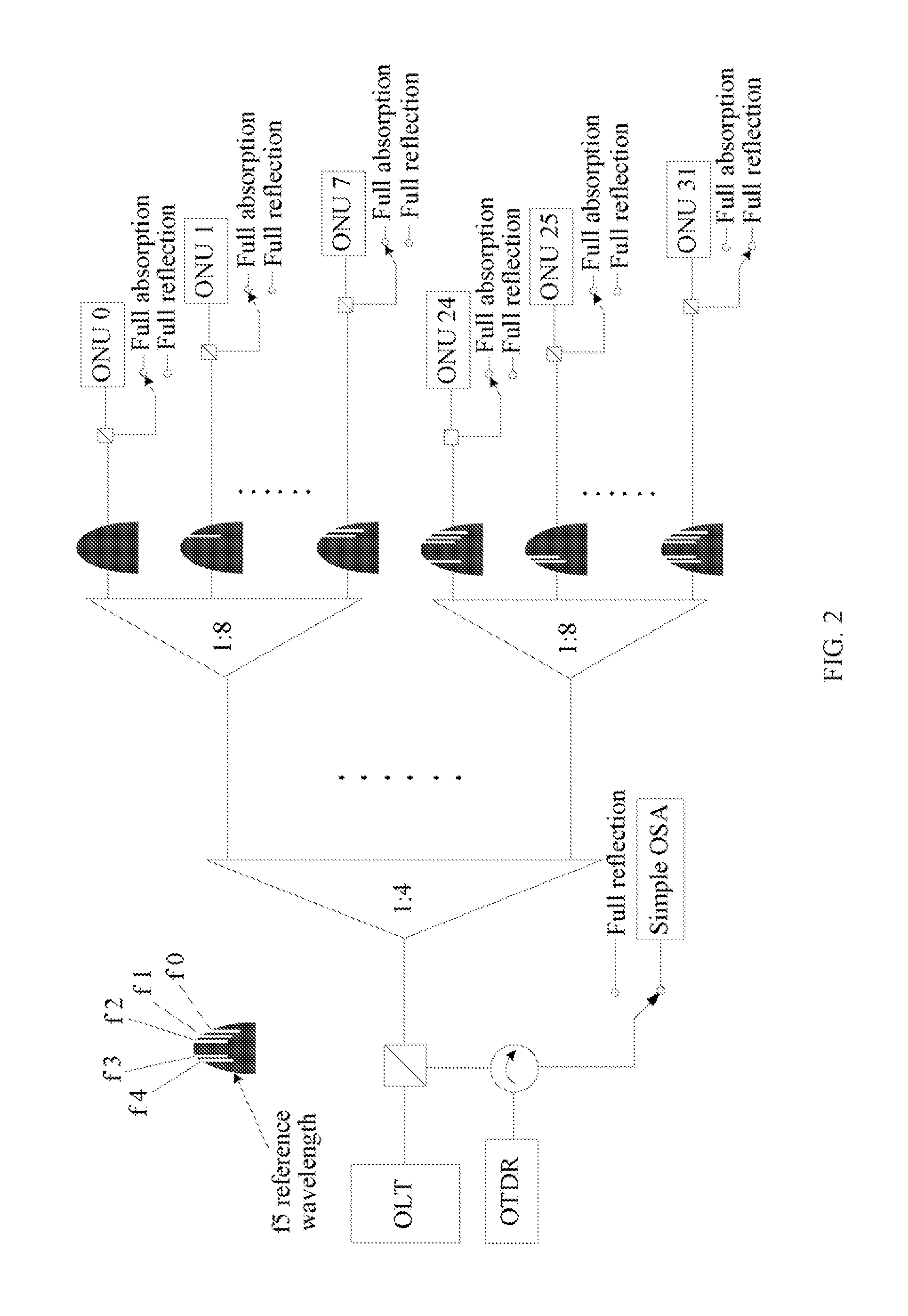
[0028]For example, in a PON system with a split ratio of 1:32, after a test signal is split by the optical splitter, 32 test signals are obtained and are then carried by 32 branch fibers respectively, and each branch fiber has a corresponding screening frequency value. In a specific embodiment, in this step, an optical signal with a filtering frequency value same as that of a branch fiber where test signal is carried is filtered out from the 32 test signals.

[0029]The filtering frequency value is a frequ...

embodiment 2

[0045]Based on the method and system for detecting branch fibers, an embodiment of the present disclosure further provides a passive optical network that applies the method and the system for detecting branch fibers. Specifically, the passive optical network system includes an optical line terminal, an optical distribution network, and a plurality of optical network units. The optical line terminal is connected to the optical network units in a point-to-multipoint manner through the optical distribution network. The passive optical network system further includes: a test device (such as an OTDR) that is configured to send test signals to physical channels of the optical network units through the optical splitter, where the test signals are respectively added, at the ports of the optical splitter, with identification information of the physical channels corresponding to the ports, and a test signal is reflected on a detected physical channel to form a reflection signal added with the...

embodiment 3

[0065]Corresponding to the method for detecting branch fibers, an embodiment of the present disclosure further provides a test device for detecting the branch fibers. As shown in FIG. 4, the test device provided by the embodiment of the present disclosure includes:

[0066]a test device 401, configured to send test signals to a plurality of branch fibers, where the test signals may be respectively added with identification information for identifying branch fibers connected to the ports during the test signals are transmitted to the branch fibers, and a test signal corresponding to a detected branch fiber is reflected at an end of the detected branch fiber to form a reflection signal added with the identification information of the detected branch fiber, and other test signals corresponding to other branch fibers are absorbed at the corresponding branch fibers;

[0067]a receiving module 402, configured to receive the reflection signal added with the identification information of the dete...


PUM


Abstract

A method for detecting branch fibers is provided, which includes: sending test signals to a plurality of branch fibers, where the test signals are added at ports of the optical splitting module with identification information for identifying branch fibers connected to the ports and receiving a reflection signal added with the identification information of a detected branch fiber, identifying the detected branch fiber corresponding to the reflection signal through detecting the identification information added to the reflection information, and obtaining channel characteristics of the detected branch fiber according to the reflection signal. Further, a system and an apparatus for detecting branch fibers are provided.

Description

CROSS-REFERENCE TO RELATED APPLICATIONS[0001]This application is a continuation of International Application No. PCT / CN2011 / 073355, filed on Apr. 27, 2011, which claims priority to Chinese Patent Application No. 201010170195.6, filed on May 11, 2010, both of which are hereby incorporated by reference in their entireties.FIELD OF TILE DISCLOSURE[0002]The present disclosure relates to passive optical network technologies, and in particular, to a method and an apparatus for detecting branch fibers, and a passive optical network system.BACKGROUND OF THE DISCLOSURE[0003]In a PON (Passive Optical Network) based on P2MP architecture, a communication device located in a central office, such as an OLT (Optical Line Terminal), receives information reported from multiple user side devices, such as multiple ONUs (Optical Network Units), in a time division multiple access (TDMA) mode.[0004]When the physical optical channel corresponding to each branch fiber is tested, a test device in the centra...

Claims


Application Information

Patent Timeline
Patent Type & Authority Patents(United States)
IPC IPC(8): H04B17/00H04B10/071
CPCH04B10/071
Inventor WEN, YUNSHENGZHAO, JUNWANG, SHIJUNSHAN, XIAOLEIWANG, BO
Owner HUAWEI TECH CO LTD
Learn More