Compact dispensing tube opener

a cutter/opener, compact technology, applied in the direction of liquid transfer devices, tubes shearing machines, tobacco, etc., can solve the problems of compromising the desired degree of perfection in the application of material beads, affecting the safety of workers, and affecting the use of dispensing tube cutting tools, etc., to achieve the effect of convenient storage in a pock

Inactive Publication Date: 2006-07-27
ACCURATE CONCEPTS
View PDF28 Cites 5 Cited by
  • Summary
  • Abstract
  • Description
  • Claims
  • Application Information

AI Technical Summary

Benefits of technology

[0008] This invention provides an opener for accessing contents of a dispensing tube having a monolithic dispensing tip that requires cutting, as well as a seal at the tip base that requires puncturing, to allow dispensing of material from the tube. The opener is user safe and allows for us...

Problems solved by technology

Obtaining the desired tube cut (at the proper angle, linearity and without burrs) using such tools is difficult at best, and thus the desired degree of perfection in the application of the material bead is compromised.
Such operations utilizing a utility knife are also hazardous for the worker.
Such heretofore suggested dispensing tube cutting tools, however, have not always improved user safety or provided for selected tube tip opening diameter, angle precision or consistency and smoothness of cuts.
Moreover, some tools heretofore suggested and/or utilized are often bulky and inconvenient or difficult to use (particularly when made part of a caulking gun).
Larger tools are always subject to being laid down after use at ...

Method used


Image

  • Compact dispensing tube opener
  • Compact dispensing tube opener
  • Compact dispensing tube opener

Examples


embodiment 200

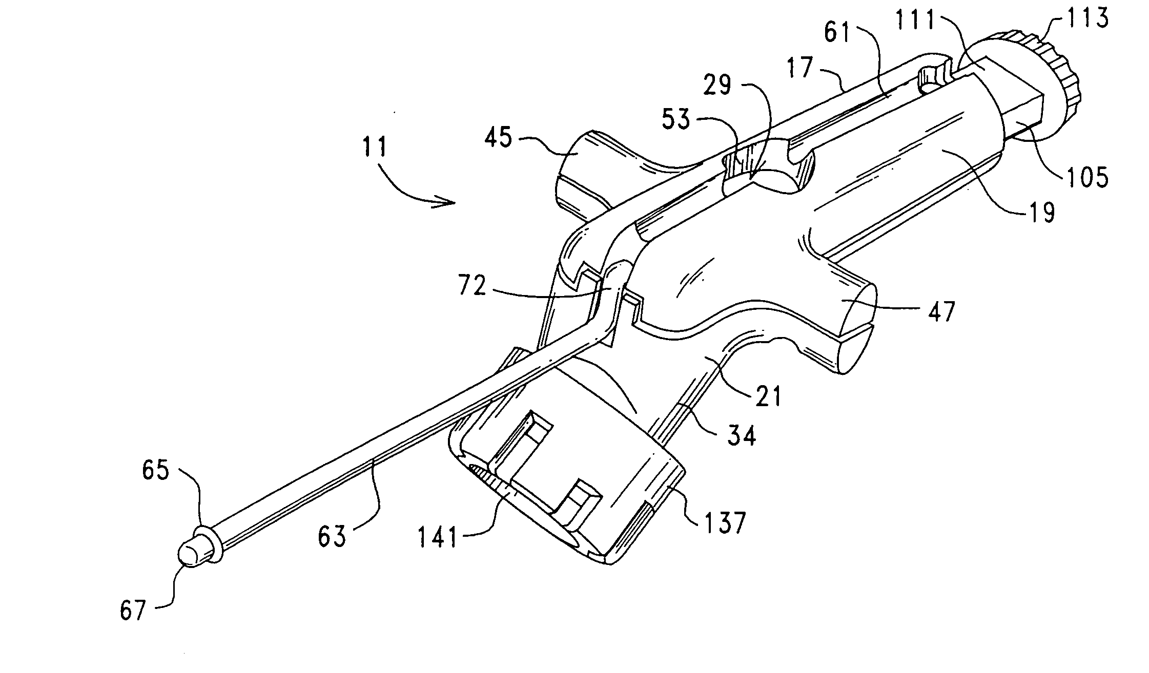
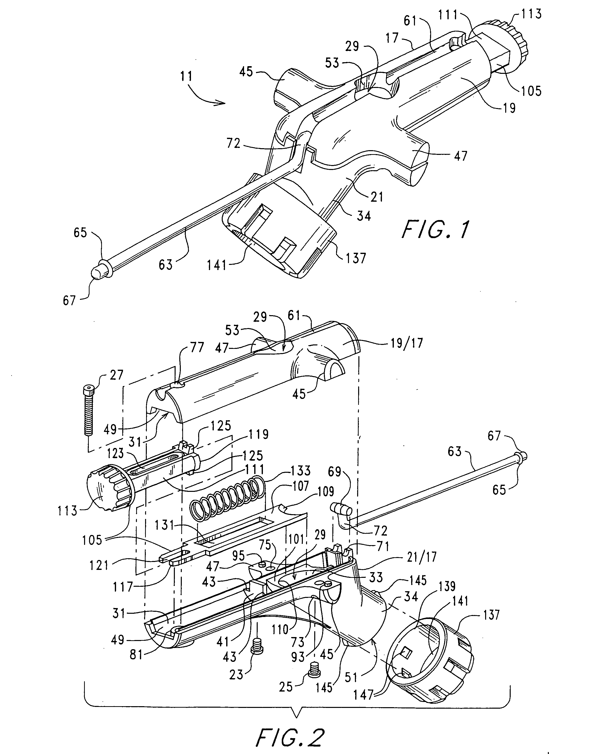
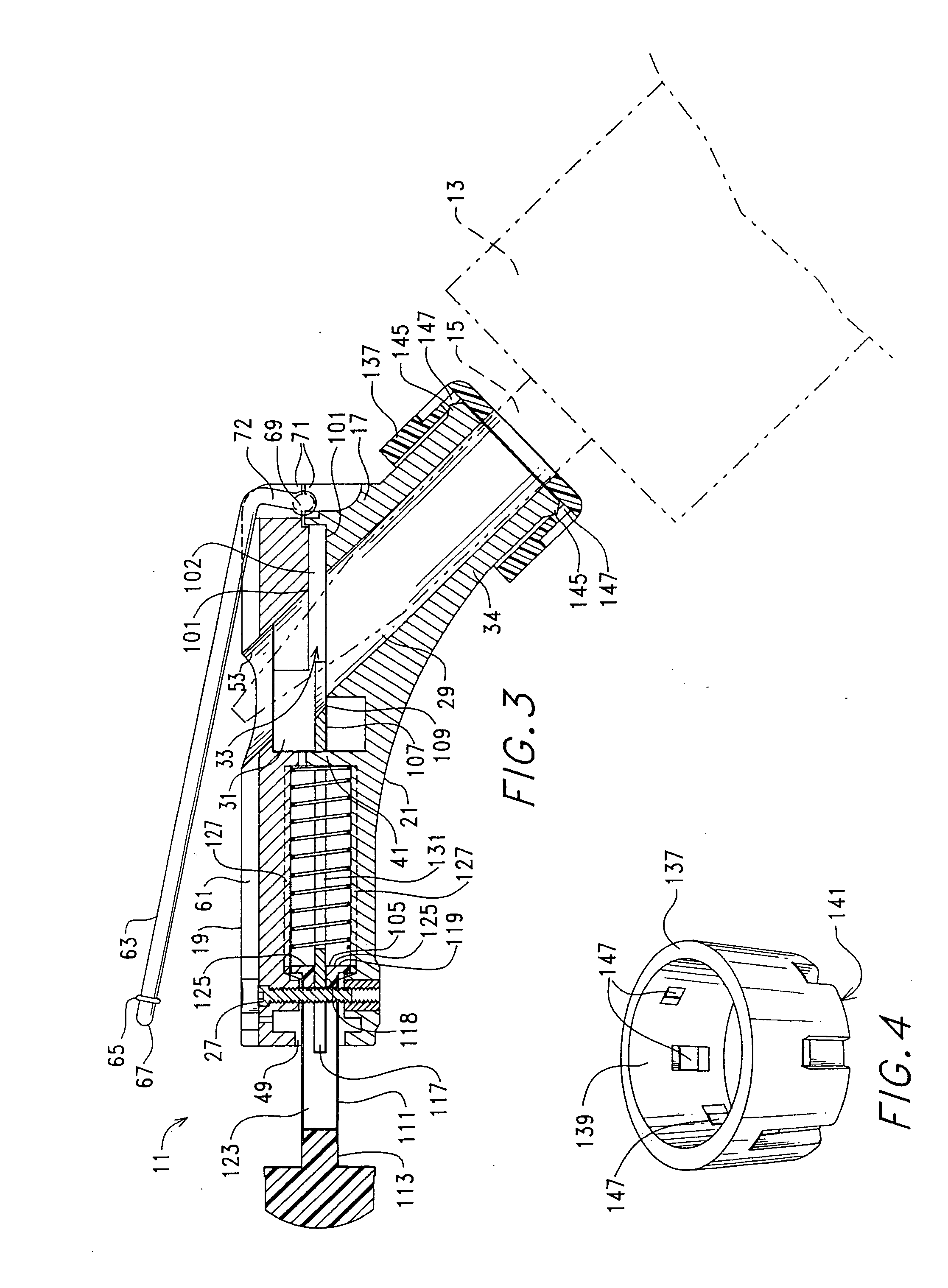
[0057]FIGS. 7 through 15 illustrate the now preferred embodiment 200 of the opener of this invention. As before, the opener is configured for accessing the contents of a dispensing tube 13 of the type having a monolithic dispensing tip 15 that requires cutting and an inner foil seal 201 that must be punctured to allow dispensing of material from the tube (see FIGS. 15 and 16).

[0058] Similar to opener 11, opener 200 is embodied in a housing 203 having a much more compact form factor. Housing 203 is defined by housing sections 205 and 207, housing section 207 having first and second case portions 209 and 211. The housing sections are secured by a combination of the form fitted and matable outer engaging peripheries of the housing sections (see FIGS. 13 and 14) and any suitable means such as mechanical snaps or, as shown, threaded connectors 213, case portion 211 stabilizing case portion 209 at overlapping lips 214 (FIG. 12). As shown in FIGS. 10, 13, 14 and 16, first and second passag...

first embodiment

[0066] As may be appreciated, the angle of cut made be the openers of this invention depends upon the angle of intersection of elongated passageways 29 and 31 (opener 11) or passageways 215 and 217 (opener 200). Thus various models of the openers configured to accommodate different cutting angles could be provided to allow cut angles (from 15° to 80°, for example). With respect to the first embodiment, an opener could be configured having two housings, each housing a different one of the passageways, and pivotably connected with each other and indexed, at the passageways' intersection for user setting of angle of cut.


PUM

PropertyMeasurementUnit
Angleaaaaaaaaaa
Angleaaaaaaaaaa
Diameteraaaaaaaaaa

Abstract

A compact dispensing tube opener for accessing contents of a dispensing tube having a dispensing tip and an inner seal. The opener includes a housing with first and second passageways therein meeting at an angle at an intersection. A blade carriage is movable in the second passageway and across the intersection at one end thereof, a manually accessible portion at an opposite end thereof extending from the housing. A cooperative guide structure at the housing and the blade carriage maintains carriage slidability within the housing during use without binding. Return springs are maintained in the housing for returning the carriage after use. A dispenser tube tip locator is slidably maintained at the housing adjacent to an opening to the first passageway and has plurality of angled passages therethrough each with a different diameter. A lance is mounted at the housing for puncturing the seal, and is pivotable into and out of a channel defined crosswise in the housing.

Description

FIELD OF THE INVENTION [0001] This invention is a continuation-in-part of U.S. patent application Ser. No. 11041,133 filed Jan. 24, 2005 by inventors herein and entitled DISPENSING TUBE OPENER.FIELD OF THE INVENTION [0002] This invention relates to openers for cylindrical tubes having a closed and sealed dispensing tip such as the type utilized for packaging and dispensing caulk or other sealants or adhesives, and, more particularly, relates to a compact cutter / opener for such dispensing tubes. BACKGROUND OF THE INVENTION [0003] Sealants such as caulk and adhesives are commonly provided in and dispensed from cylindrical tubes having a monolithic tapering (elongated conical, for example) plastic dispensing tip that is closed at its outermost tapered end upon delivery to an end user. Such tubes also commonly include a plastic / foil seal at the interface between the tube and dispensing tip. The dispensing tip must be cut and the foil seal punctured before any product can be dispensed fr...

Claims


Application Information

Patent Timeline
IPC IPC(8): B26B17/00B67D99/00
CPCB05C17/00503B05C17/0052B05C17/0143B26D1/04B26D1/08B26D3/02B05C17/00596
Inventor WHITEMILLER, ANTHONY F.ANGSTEAD, RONALD A.BERTSCH, PATRICK M.MURRAY, BRENT W.
Owner ACCURATE CONCEPTS
Why Eureka
Try Eureka