Reciprocating tool attachment assembly and methods

Inactive Publication Date: 2014-12-30
WILCHER JAMES TIMOTHY
View PDF37 Cites 15 Cited by
  • Summary
  • Abstract
  • Description
  • Claims
  • Application Information

AI Technical Summary

Problems solved by technology

One problem associated with conventional reciprocating tools is the placement of the tool chuck near the centerline of the tool body.
A lateral offset between the edge of the tool and the attached instrument creates difficulty in using a conventional reciprocating tool to operate on a workpiece in a corner or in applications where a flush cut near a planar or curved surface is desired.
Generally, in some applications, the offset between the tool chuck and the edge of the tool in conventional reciprocating tools makes it impossible for a user to position an attached instrument directly against or parallel to a surface for operating on an adjacent workpiece that that extends from or is positioned near the surface.
However, some previous attempts provide only an adapter that extends from the tool chuck.
Conventional offset configurations in some applications can create a bending moment about the tool chuck and can cause unstable forces acting upon the reciprocating t

Method used


Image

  • Reciprocating tool attachment assembly and methods
  • Reciprocating tool attachment assembly and methods
  • Reciprocating tool attachment assembly and methods

Examples


Embodiment Construction

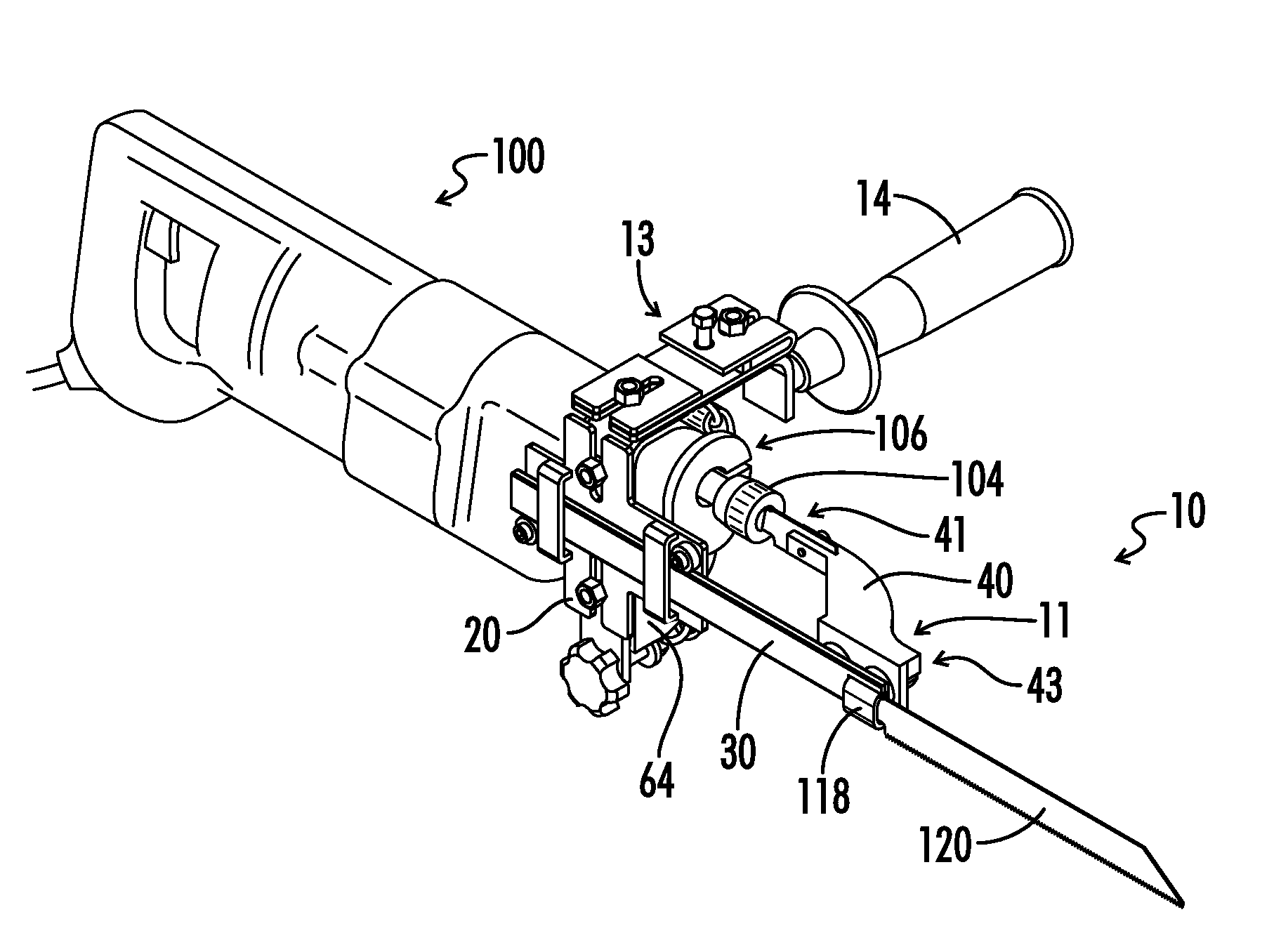
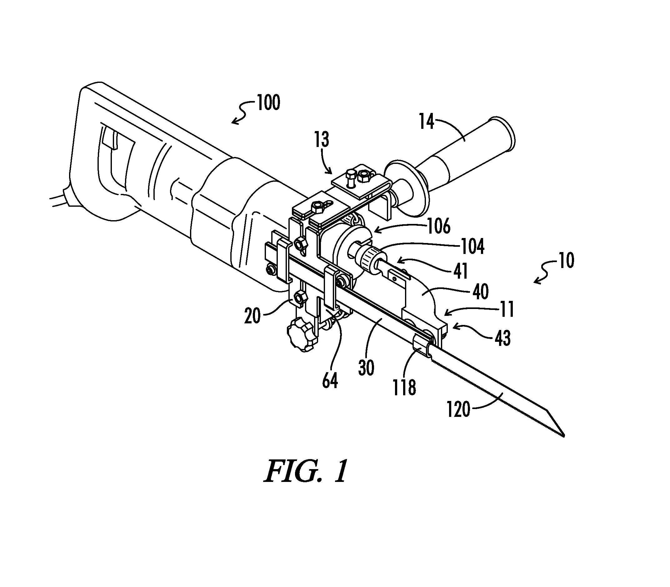
[0032]Referring now to the drawings, FIG. 1 illustrates a perspective view of one embodiment of a reciprocating tool attachment including a reciprocating tool attachment apparatus generally designated by the numeral 10. In the drawings, not all reference numbers are included in each drawing, for the sake of clarity. In addition, positional terms such as “upper,”“lower,”“side,”“top,”“bottom,” etc. refer to the apparatus when in the orientation shown in the drawing. A person of skill in the art will recognize that the apparatus can assume different orientations when in use.

[0033]Referring further to FIG. 1, one embodiment of a reciprocating tool attachment 10 is generally illustrated. Reciprocating tool attachment 10 is attached to a reciprocating tool 100. The reciprocating tool attachment 10 in some embodiments includes a neck mount assembly 13 and a tool holder apparatus 11. Tool holder apparatus 11 can also be described as an offset tool holder. Reciprocating tool attachment 10 ca...


PUM


Abstract

An attachment apparatus for a reciprocating tool provides a tool holder having an angled bracket and a guide rod extending from the angled bracket. The guide rod can engage a travel slot on the reciprocating tool. An instrument such as a saw blade can be attached to the angled bracket or guide rod. The guide rod stabilizes the instrument during use. The travel slot can be defined integrally on the reciprocating tool or on an attachment to the tool. In some embodiments, a neck mount assembly is attached to the neck on the reciprocating tool. The neck mount assembly can include a frame and a guide plate. The guide plate can include a travel slot shaped for receiving the guide rod.

Description

BACKGROUND OF THE INVENTION[0001]1. Technical Field[0002]The present invention relates generally to handheld power tools. More particularly, the present invention relates to attachments and methods for use with reciprocating tools.[0003]2. Background Art[0004]Reciprocating tools known in the art generally provide a handheld tool body that houses a motor and a gear or cam transmission for translating rotary motion of the motor shaft into reciprocating linear motion. A reciprocating tool chuck is typically attached to the gear transmission or cam for securing a removable blade or other modular instrument to the tool. In some conventional applications a chisel or an edged tool such as a cutting instrument can be secured to the tool chuck. In other embodiments, a hammer or other blunt instrument can be attached to the tool chuck for driving nails or breaking up materials.[0005]One problem associated with conventional reciprocating tools is the placement of the tool chuck near the center...

Claims


Application Information

Patent Timeline
IPC IPC(8): B27B19/00B27B3/26
CPCB23D51/10B23D17/00B23D29/005B23D49/11B23D51/02Y10T279/3406Y10T279/3418B26B15/00B26D7/2614
Inventor WILCHER, JAMES, TIMOTHY
Owner WILCHER JAMES TIMOTHY
Why Eureka
Try Eureka