Solid-state light-emitting element drive device, lighting system and lighting fixture

a drive device and light-emitting element technology, applied in the direction of electric variable regulation, process and machine control, instruments, etc., can solve the problems of increasing switching loss and significantly higher frequency, and achieve the effect of preventing the switching frequency from increasing

Inactive Publication Date: 2014-12-30
PANASONIC INTELLECTUAL PROPERTY MANAGEMENT CO LTD
View PDF23 Cites 0 Cited by
  • Summary
  • Abstract
  • Description
  • Claims
  • Application Information

AI Technical Summary

Benefits of technology

[0009]It is an object of the present invention to provide a solid-state light-emitting element drive device, which can change smoothly a light output of a solid-state light-emitting element with respect to a change in a duty cycle of the burst dimming while preventing the switching frequency from increasing, and a lighting system and a lighting fixture using the same.
[0021]The solid-state light-emitting element drive device, the lighting system and the lighting fixture of another aspect of the invention increase or decrease the accumulated value of the ON-periods of the switching element so as to be linked to a minimum variation width for the duty cycle regardless of a timing of a change in the duty cycle (dimming level) of the dimming signal for the burst dimming. Therefore, the solid-state light-emitting element drive device, the lighting system and the lighting fixture has the effect of changing smoothly a light output of the solid-state light-emitting element with respect to the change in the duty cycle of the burst dimming while preventing the switching frequency from increasing.

Problems solved by technology

However, the conventional LED drive device that adopts the Burst Dimming Method has the problem that causes interference with video equipment, such as a video camera, thereby generating flicker.
Therefore, when a frequency of a burst signal is adapted to the above-mentioned technical standards, the following problem is generated with combination of the step-down chopper circuit and the drive device: even if the duty cycle of the burst signal is changed during an OFF-period of the switching element in the step-down chopper circuit, the inductor current does not change (See FIG. 5A), and as a result, it means that the light output of the LED changes along a tiered line with respect to a change in the duty cycle of the burst signal, as shown in FIG. 5B.
However, increasing the switching frequency leads to an increase in the switching loss, and further when considering the performance of the drive circuit driving the switching element, making significantly higher frequency can't be expected.

Method used


Image

  • Solid-state light-emitting element drive device, lighting system and lighting fixture
  • Solid-state light-emitting element drive device, lighting system and lighting fixture
  • Solid-state light-emitting element drive device, lighting system and lighting fixture

Examples


first embodiment

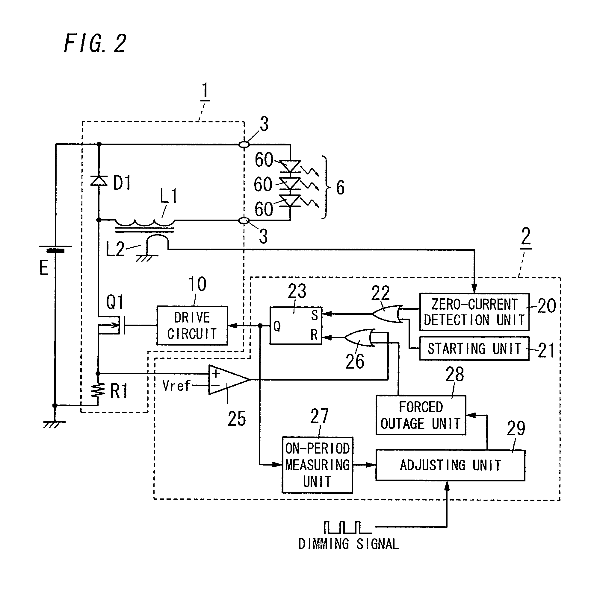
[0029]As shown in FIG. 2, a lighting system according to the present embodiment includes: a light source 6 configured by a series circuit in which a plurality of LEDs 60 are connected in series; and a solid-state light-emitting element drive device (hereinafter, referred to as an LED drive device). The LED drive device converts DC voltage / current supplied from a DC power source E to DC voltage / current for the light source 6 and drives (light) the light source 6.

[0030]The LED drive device according to the present embodiment includes a switching source circuit 1 and a control circuit 2. Then, the light source 6 is connected between output terminals 3 of the switching source circuit 1. The DC power source E applies DC voltage between input terminals of the switching source circuit 1. The switching source circuit 1 is a well-known step-down chopper circuit that includes a switching element Q1, a diode D1 (a regenerative element), an inductor L1, a drive circuit 10 and the like. The swit...

second embodiment

[0047]FIG. 3 shows a circuit configuration diagram of an LED drive device and a lighting system according to the present embodiment. Here, the basic constituent elements of the present embodiment are similar to those of First Embodiment. Therefore, such elements are assigned with same reference numerals and the explanation thereof will be omitted.

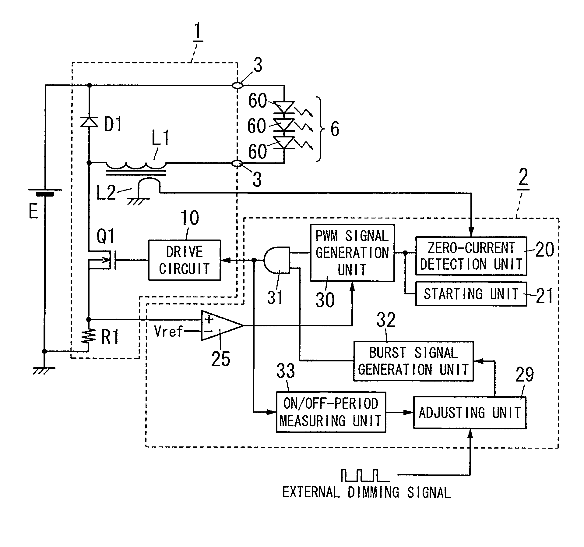
[0048]A control circuit 2 according to the present embodiment includes a zero-current detection unit 20, a starting unit 21, a comparator 25, an adjusting unit 29, a PWM signal generation unit 30, an AND gate 31, a burst signal generation unit 32, and an ON / OFF-period measuring unit 33.

[0049]The PWM signal generation unit 30 outputs the PWM signal when the detection signal is inputted from the zero-current detection unit 20 or the starting signal is inputted from the starting unit 21, and then stops outputting the PWM signal when the output of the comparator 25 becomes the high level.

[0050]The AND gate 31 calculates a logical AND of the PWM...


PUM


Abstract

In a conventional example, even if a duty cycle of the burst dimming is changed during an OFF-period of a switching element, current flowing to an LED is maintained constant. On the other hand, in the present embodiment, an accumulated value of ON-periods of a switching element is increased or decreased so as to be linked to a minimum variation width for a duty cycle (a dimming level) of a dimming signal, regardless of a timing of when the duty cycle is changed. Therefore, a lighting system (an LED drive device) according to the present embodiment can change smoothly a light output of a solid-state light-emitting element (a light source) with respect to a change in a duty cycle of the burst dimming while preventing the switching frequency from increasing.

Description

BACKGROUND OF THE INVENTION[0001]1. Field of the Invention[0002]The invention relates generally to solid-state light-emitting element drive devices, lighting systems and lighting fixtures and, more particularly, to a solid-state light-emitting element drive device that drives a solid-state light-emitting element, such as a light-emitting diode or an organic electroluminescence (EL) element, to emit light, and a lighting system and a lighting fixture that use the drive device.[0003]2. Description of the Related Art[0004]In recent years, a lighting system and a lighting fixture have rapidly become widely used, which adopts, as a light source, a solid-state light emitting element such as a light-emitting diode or an organic electroluminescence (EL) element, as substitute for an incandescent lamp and a fluorescent lamp. For example, Japanese Unexamined Patent Application Publication (Translation of PCT Application) No. 2006-511078 discloses an LED drive device that adopts, as a light so...

Claims


Application Information

Patent Timeline
Patent Type & Authority Patents(United States)
IPC IPC(8): H05B33/08H05B44/00
CPCH05B33/0851H05B33/0821H05B45/327H05B45/40H05B45/14
Inventor NARUO, MASAHIROESAKI, SANAFUKUDA, KENICHI
Owner PANASONIC INTELLECTUAL PROPERTY MANAGEMENT CO LTD
Why Eureka
Try Eureka