Display apparatus and touch detection apparatus

a technology of touch detection and display apparatus, which is applied in the field of display apparatus and touch detection apparatus, can solve the problems of degrading operability and increasing power consumption, and achieve the effect of improving responsibility and reducing latency

Active Publication Date: 2010-11-25
JAPAN DISPLAY INC
View PDF7 Cites 78 Cited by
  • Summary
  • Abstract
  • Description
  • Claims
  • Application Information

AI Technical Summary

Benefits of technology

[0014]The present invention provides a display apparatus having a function of touch detection wherein the latency is reduced and the responsibility is improved without increasing the detection driving frequency. Further, the present invention provides a touch detection apparatus having a function of the touch detection.
[0024]In summary, with the display apparatus and the touch detection apparatus, the latency can be reduced to improve the responsibility without raising the detection driving frequency.

Problems solved by technology

If the delay is long, then this degrades the operability.
However, if the driving frequency or the like upon detection scanning is increased to raise the speed of the detection scanning in the touch detection apparatus, then power consumption increases.

Method used


Image

  • Display apparatus and touch detection apparatus
  • Display apparatus and touch detection apparatus
  • Display apparatus and touch detection apparatus

Examples


first embodiment

1. First Embodiment

Basic Configuration and Operation of Touch Detection

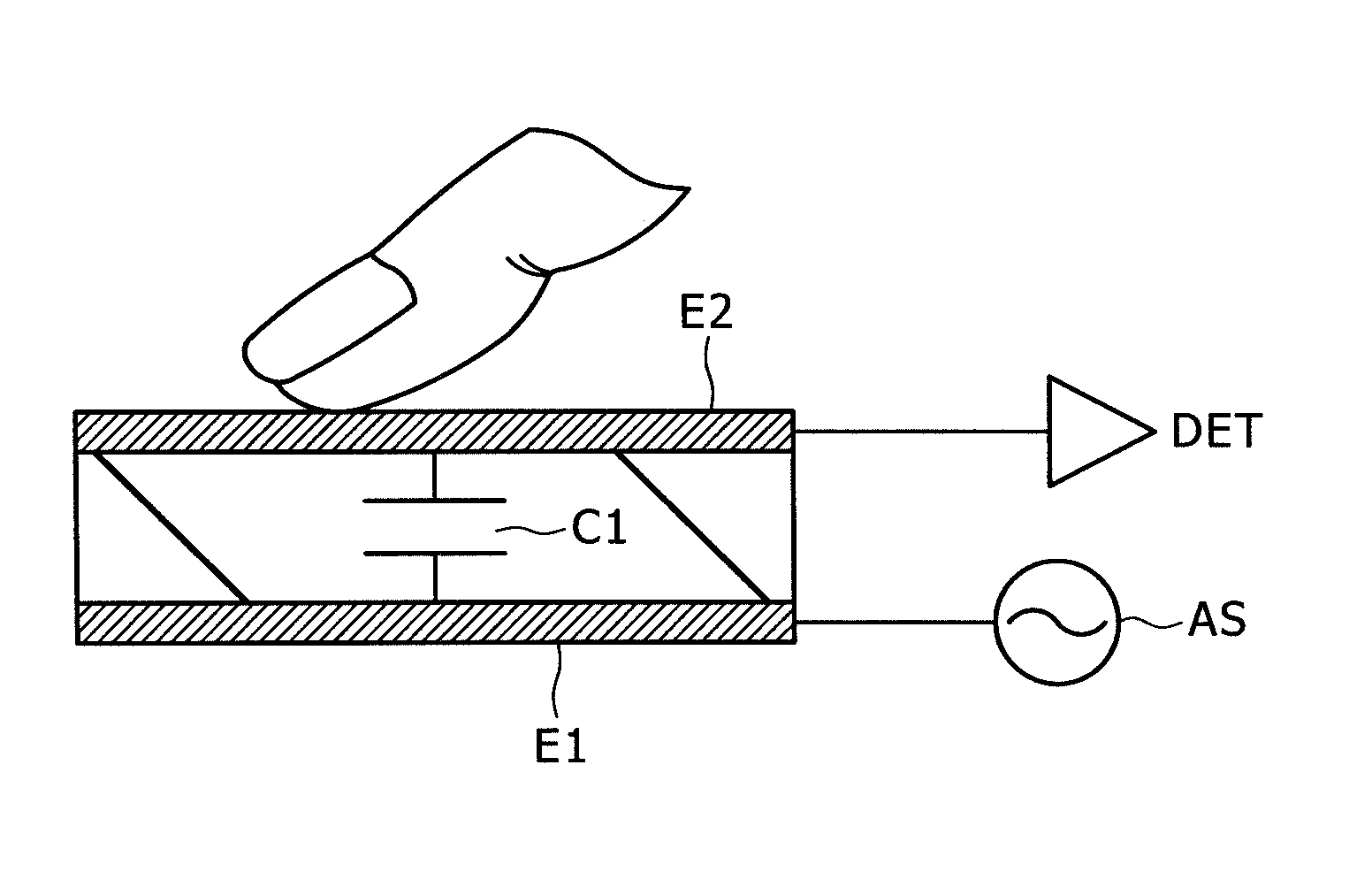
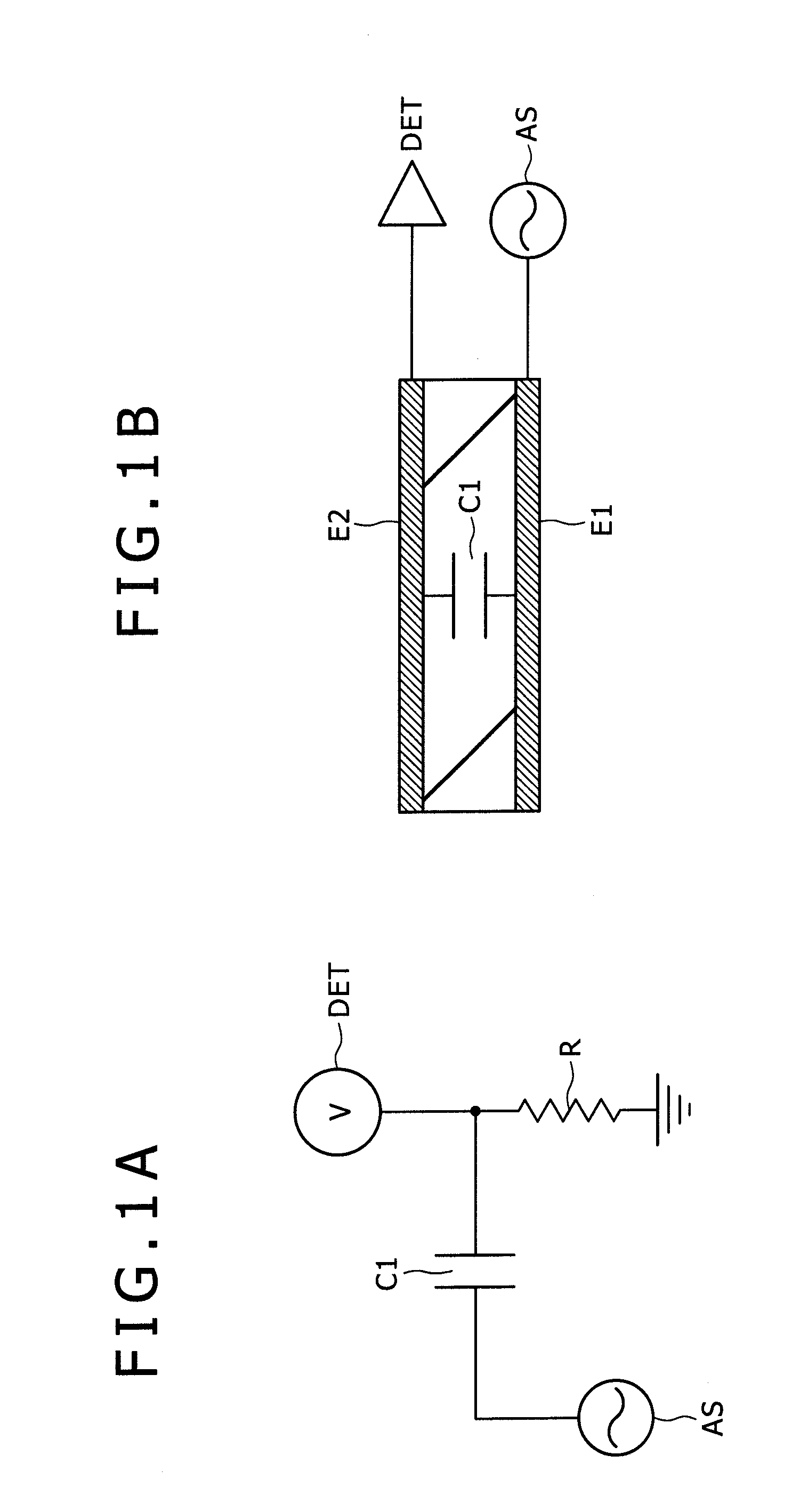
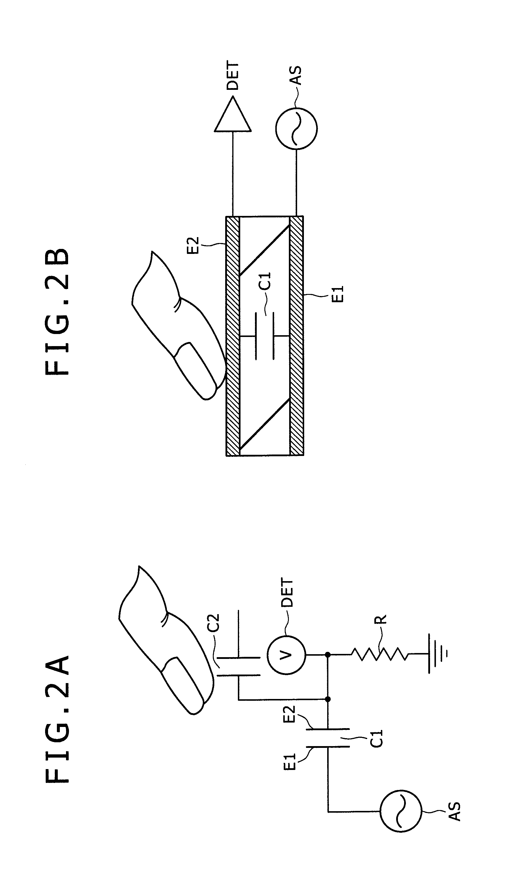
[0055]First, as a matter which is a prerequisite to the first embodiment but is common to the other embodiment, a basis of capacitance type touch detection is described with reference to FIGS. 1A to 3C.

[0056]FIGS. 1A and 2A are equivalent circuit diagrams of a touch sensor section and FIGS. 1B and 2B are structure views (schematic sectional views) of the touch sensor section. Here, FIGS. 1A and 1B show a case wherein a finger as a detection target is not proximate to a sensor and FIGS. 2A and 2B show another case wherein the finger touches with or approaches the sensor.

[0057]The touch sensor section shown in FIGS. 1A and 2A is a capacitance type touch sensor and is formed from a capacitance element as shown in FIGS. 1B and 2B. In particular, a capacitance element (capacitance) C1 is formed from a dielectric D and a pair of electrodes disposed in an opposing relationship in such a manner as to sandwich the dielect...

second embodiment

2. Second Embodiment

[0106]The second embodiment relates to a display apparatus according to the present invention. The display apparatus has a touch sensor function same as that of the display apparatus of the first embodiment.

[0107]The display apparatus according to the present embodiment is a liquid crystal display apparatus which uses Vcom driving.

[0108]The present invention does not essentially require the Vcom driving. However, the liquid crystal display apparatus described below is generally configured such that it uses the Vcom driving and uses a common electrode or opposing electrode for display driving also for sensor driving to carry out display scanning or writing scanning and sensor driving scanning simultaneously.

[0109]At this time, the display driving and the detection driving are preferably synchronized with each other. In other words, in the present embodiment, a driving electrode for the display driving, that is, an opposing electrode, is used also as a driving elec...


PUM


Abstract

A display apparatus includes: a display face; a display function layer adapted to vary display on the display face in response to an inputted image signal; a plurality of driving electrodes disposed separately in one direction; a detection scanning control section configured to apply a detection driving voltage to some of the plural driving electrodes and carry out detection driving scanning while shifting an application object of the detection driving voltage in the one direction on the display face and then control the detection driving scanning such that jump shift of carrying out shift with a pitch of twice or more times a driving electrode pitch is included; and a plurality of sensor lines disposed separately in a direction different from the one direction and responding to touch or proximity of a detection object with or to the display face to exhibit an electric variation.

Description

[0001]The present application claims priority to Japanese Patent Application JP 2009-120614 filed in the Japan Patent Office on May 19, 2009, and Japanese Priority Patent Application JP 2010-063024 filed in the Japan Patent Office on Mar. 18, 2010, the entire contents of which are hereby incorporated by reference.BACKGROUND OF THE INVENTION[0002]1. Field of the Invention[0003]The present invention relates to a display apparatus having a function for detecting touch or proximity of a finger, a pen or the like with or to a detection face by the user, that is, a function of touch detection such as a touch panel or a like apparatus. The present invention further relates to a touch detection apparatus having the touch detection function.[0004]2. Description of the Related Art[0005]For a touch detection method for a touch panel, three types including an optical type, a resistance film type and a capacitance type are known.[0006]Meanwhile, in order to associate electrical variation occurri...

Claims


Application Information

Patent Timeline
Patent Type & Authority Applications(United States)
IPC IPC(8): G06F3/041
CPCG02F1/13338G06F3/0412G06F3/044G09G2300/0434G09G3/3655G09G3/3677G09G3/3614G06F3/04166G06F3/0445G06F3/0446G06F3/0416G02F2201/123G06F2203/04101
Inventor TAKEUCHI, TAKEYANOGUCHI, KOUJIISHIZAKI, KOJITERANISHI, YASUYUKINAKANISHI, TAKAYUKI
Owner JAPAN DISPLAY INC
Why Eureka
Try Eureka