Energy harvesting by means of thermo-mechanical device utilizing bistable ferromagnets

a ferromagnetic and thermo-mechanical technology, applied in the direction of mechanical equipment, generators/motors, machines/engines, etc., can solve the problems of small temperature differences that produce little energy and efficiency, and achieve the effects of increasing operational frequency, improving piezoelectric/electroactive element design, and increasing available energy

Inactive Publication Date: 2009-12-24
RGT UNIV OF CALIFORNIA
View PDF13 Cites 74 Cited by
  • Summary
  • Abstract
  • Description
  • Claims
  • Application Information

AI Technical Summary

Benefits of technology

[0012]An objective of the present invention is to provide an approach for increased available energy, and for increased operational frequency. The former can be achieved by improved designs of piezoelectric / electroactive elements, and solenoids. In addition, better efficiency and power output can be achieved by using exotic ferromagnetic materials which have high saturation magnetization values and high thermal conduction properties.

Problems solved by technology

While useful, these materials 2 0 produce little energy and efficiency for small temperature differences.

Method used


Image

  • Energy harvesting by means of thermo-mechanical device utilizing bistable ferromagnets
  • Energy harvesting by means of thermo-mechanical device utilizing bistable ferromagnets
  • Energy harvesting by means of thermo-mechanical device utilizing bistable ferromagnets

Examples


second embodiment

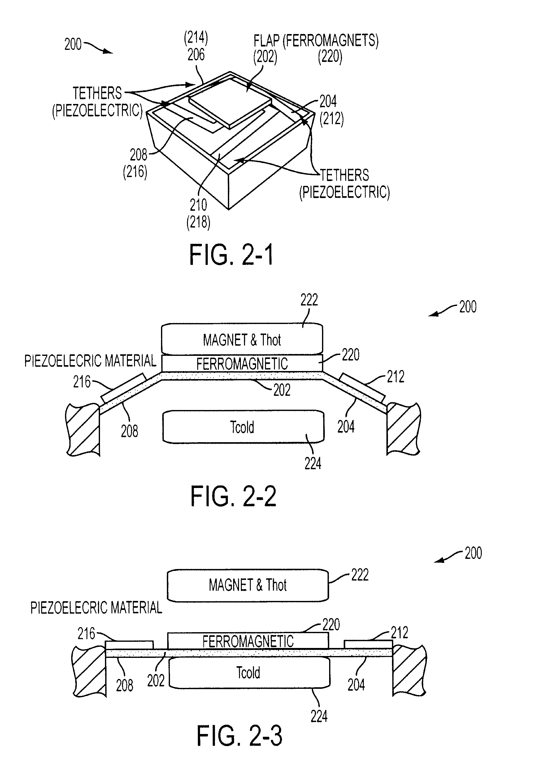
[0023]FIG. 2-1 shows an energy harvesting device 200 according to the present invention. In FIG. 2-1, the apparatus 200 is composed of a flap 202 with tethers (204, 206, 208, 210) which restrain the motion in the vertical direction only, a piezoelectric layer (212, 214, 216, 218) which is attached to the tethers where stress / strain is generated, and a ferromagnetic layer 220 on flap 202. This deign can allow faster frequency by eliminating the heat transfer though piezoelectric materials which have low thermal conduction coefficients. In addition, this design does not incorporate SMA and relies on the bending of the tether elements for a restoring force. It is believed that this design surpasses any thermoelectric device in the area of efficiency. The limiting efficiency of the best research-level super-lattice thermoelectric material is less than 20% for ΔT<100K. On the other hand, the limiting efficiency of the current invention can potentially reach more than 25%, which is calcul...

third embodiment

[0026]FIG. 3-1 shows an energy harvesting device 300 according to the present invention. In FIG. 3-1, the apparatus 300 is composed of a heat source with a hard magnet 302, a cooling side 304, a ferromagnetic material 306 which has restrained motion in the vertical direction only, a secondary hard magnet 308, and an electromagnetic induction coil 310 which is wrapped around the magnetic path 312. This design can allow faster frequency by eliminating the heat transfer through extra materials. It is also possible to reduce the device cost. In this stage, the temperature of the ferromagnetic material 306 is less than TC, so the ferromagnetic material is attracted to the heat source 302. The magnetic path can be considered as open in this situation.

[0027]In FIG. 3-2, the ferromagnetic material is on the cooling side 304 by a spring mechanism or gravity. In this stage, the temperature of the ferromagnetic material is more than Tc, and it is being cooled. When the magnetic path closes, th...


PUM


Abstract

An inventive energy harvesting apparatus may include a ferromagnetic material and/or a shape memory alloys to convert thermal energy to mechanical energy to electrical energy. The apparatus is subjected to a thermal gradient to cause beams to bend thus creating stress/strain in a piezoelectric material, or creating magnetic flux in a magnetic path. The charges created in this process can be transferred to electrical batteries.

Description

CROSS-REFERENCE OF RELATED APPLICATION[0001]This application claims priority to U.S. Provisional Application No. 60 / 761,789 filed Jan. 25, 2006, the entire contents of which are hereby incorporated by reference.[0002]The U.S. Government has a paid-up license in this invention and the right in limited circumstances to require the patent owner to license others on reasonable terms as provided for by the terms of AFOSR funding under Grant No. FA9550-04-1-0067.BACKGROUND[0003]1. Field of Invention[0004]Embodiments of the present invention relate to thermal energy harvesting (or thermal energy scavenging) techniques using ferromagnetic materials which provide a mechanical motion and piezoelectric, electroactive, electromagnetic, and / or magnetostrictive generator which converts the mechanical energy into electrical energy. In addition, shape memory alloys can be added to obtain enhanced operational effects.[0005]2. Discussion of Related Art[0006]The contents of all references, including a...

Claims


Application Information

Patent Timeline
Patent Type & Authority Applications(United States)
IPC IPC(8): H02K7/18F03G7/06
CPCF03G7/065H01L41/1134H02N3/00H02N2/18H01L41/1136H02K35/06H10N30/304H10N30/306H02K39/00H10N30/00H10N30/30
Inventor UJIHARA, MOTOKILEE, DONG-GUNCARMAN, GREGORY P.
Owner RGT UNIV OF CALIFORNIA
Why Eureka
Try Eureka