Method and system for warming up catalytic converter for cleaning up exhaust gas
a catalytic converter and exhaust gas technology, which is applied in the direction of mechanical equipment, machines/engines, electric control, etc., can solve the problems of engine with a turbocharger taking a longer time to warm up the catalytic converter, low temperature of exhaust gas, and certain time, so as to promote the catalytic reaction, increase the heat contained in exhaust gas, and reduce the loss of thermal energy that the exhaust gas flowing toward the catalytic converter undergoes
- Summary
- Abstract
- Description
- Claims
- Application Information
AI Technical Summary
Benefits of technology
Problems solved by technology
Method used
Image
Examples
first embodiment
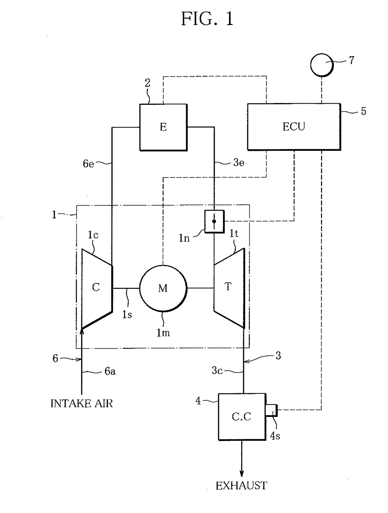
[0034]FIG. 1 is a diagram schematically showing a warming-up system according to the present invention. This warming-up system is used to warm up a catalytic converter 4. The catalytic converter 4 has a function of cleaning up exhaust gas of an internal combustion engine (hereinafter referred to as “engine”) 2 mounted on an automobile, and arranged in an exhaust passage 3 of the engine 2. The engine 2 may be either a diesel engine or a gasoline engine.
[0035]In the present embodiment, the catalytic converter 4 is a three-way catalytic converter capable of removing toxic substances (typically, hydrocarbons, carbon monoxide and nitrogen oxides) from exhaust gas. The warming-up system according to the present invention is however applicable to catalytic converters other than the three-way catalytic converter.
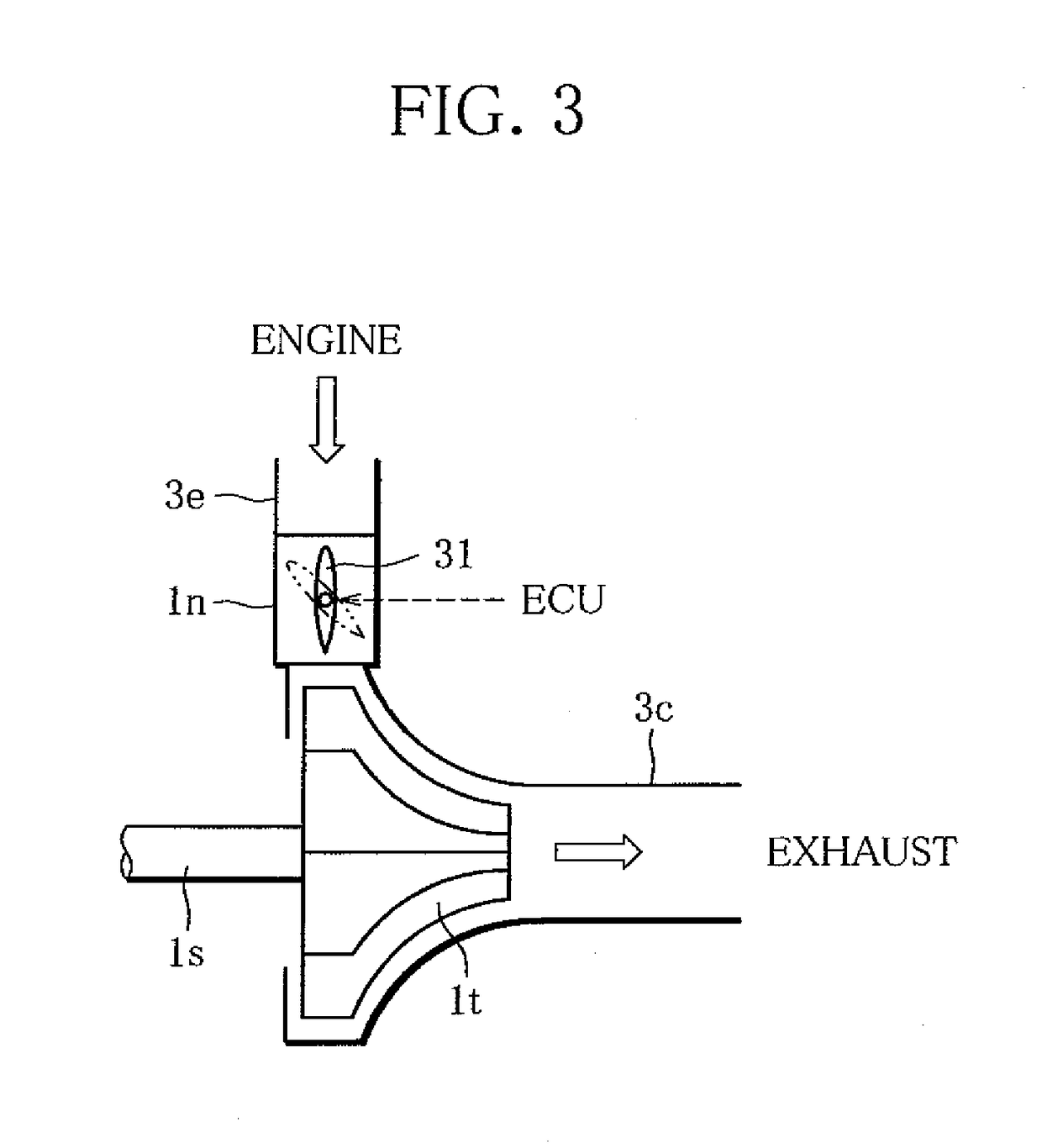
[0036]The engine 2 is provided with a turbocharger 1, and the turbocharger 1 includes a turbine 1t. The turbine 1t is arranged in the exhaust passage 3, upstream of the catalytic co...
second embodiment
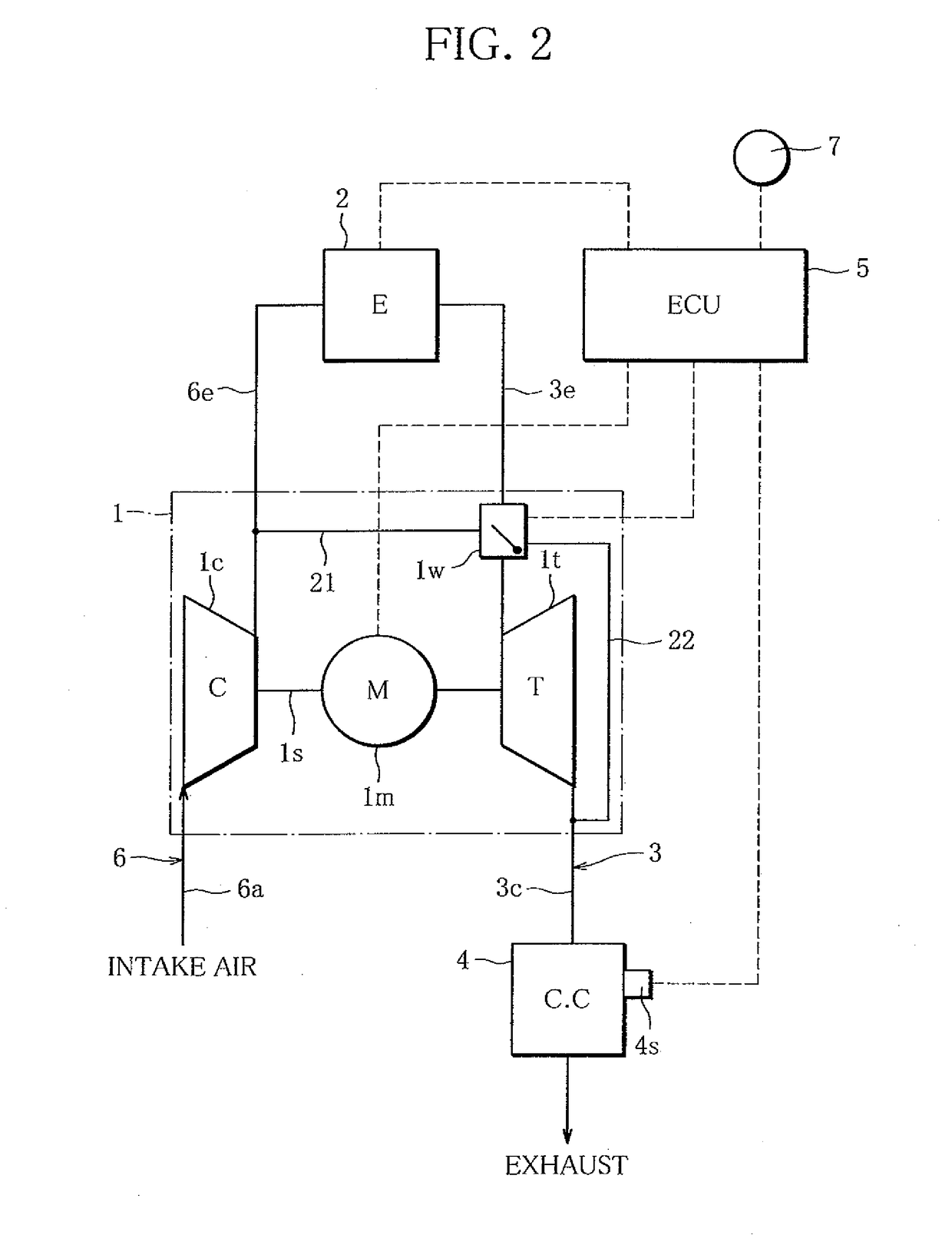
[0051]FIG. 2 schematically shows a warming-up system according to a
[0052]In FIG. 2, the same elements as those of the warming-up system according to the first embodiment are assigned the same reference characters. The description of those elements will be omitted. Also with respect to warming-up systems according to a third and subsequent embodiments, the same elements as those of the warming-up system according to the first embodiment are assigned the same reference characters in the drawings to avoid repetitive description.
[0053]The warming-up system of FIG. 2 includes a wastegate valve 1w in place of the aforementioned variable nozzle in. The wastegate valve 1w can regulate the amount of exhaust gas entering the turbine 1t. Specifically, the wastegate valve 1w is arranged in the exhaust passage 3, upstream of the turbine lt. The wastegate valve 1W is connected to a branch passage 21 and a bypass passage 22. The branch passage 21 connects the wastegate valve 1w to the downstream s...
third embodiment
[0083]FIG. 6 schematically shows a warming-up system according to a
[0084]The warming-up system of FIG. 6 includes a bypass passage 51 extending from the downstream section 6e of the intake passage 6. The bypass passage 51 is connected to the downstream section 3c of the exhaust passage 3, between the turbine 1t and the catalytic converter 4. A bypass valve 52 is inserted into the bypass passage 51. The bypass valve 52 is a solenoid valve and electrically connected to the ECU 5 so that the ECU 5 can control the bypass valve 52 to open or close.
[0085]When the ECU 5 opens the bypass valve 52 according to optional timing, part of air flowing toward the engine 2 enters the downstream section 3c of the exhaust passage 3 and is supplied to the catalytic converter 4 as secondary air. Because of such secondary air, the catalytic converter 4 is supplied with an increased amount of oxygen, which promotes catalyzed reaction on the catalytic converter 4, resulting in a rise in temperature of the...
PUM
 Abstract
Description
Claims
Application Information
 - R&D
- Intellectual Property
- Life Sciences
- Materials
- Tech Scout
- Unparalleled Data Quality
- Higher Quality Content
- 60% Fewer Hallucinations
Browse by: Latest US Patents, China's latest patents, Technical Efficacy Thesaurus, Application Domain, Technology Topic, Popular Technical Reports.
© 2025 PatSnap. All rights reserved.Legal|Privacy policy|Modern Slavery Act Transparency Statement|Sitemap|About US| Contact US: help@patsnap.com


