Radar apparatus and method of detecting target object

a target object and radar technology, applied in the field of radar apparatus and a method, can solve the problems of difficult to discriminate a target object in a vertical direction, influence of clutter, unsuitable for practical use, etc., and achieve the effect of reducing clutter and reducing time length

Inactive Publication Date: 2014-12-30
FURUNO ELECTRIC CO LTD
View PDF29 Cites 5 Cited by
  • Summary
  • Abstract
  • Description
  • Claims
  • Application Information

AI Technical Summary

Benefits of technology

[0007]The present invention is made in view of the situations as described above, and provides a radar apparatus for discharging a transmission beam while rotating an antenna, and a method of detecting a target object, that help discriminate a component within a reception signal of a target object from, such as, a clutter without requiring a long time for transceiving at each azimuth.
[0021]According to the aspects of the present invention, the azimuth, the distance and the elevation / depression angle of the reflective body is detected, and therefore, discrimination of a target object signal component from, for example, a clutter becomes easy. A time length required for transceiving signals at various azimuths is prevented from being long by scanning in the elevation / depression angle direction with the transmission beam and not by increasing the number of pulses in the transceiving due to the detection of the elevation / depression angle as above.

Problems solved by technology

Generally, in a fan beam type radar apparatus, it has been difficult to discriminate a target object in a vertical direction.
Therefore, the influence of clutters that widely spread in a height direction, such as rain, is big and is a source of problem.
Thereby, the time for detecting a target object at each azimuth becomes longer as the number of the transceiving of the pulse signals increases, therefore, it is not suitable for a practical use, such as on a ship where monitoring in a wide range around an antenna is required.

Method used


Image

  • Radar apparatus and method of detecting target object
  • Radar apparatus and method of detecting target object
  • Radar apparatus and method of detecting target object

Examples


first embodiment

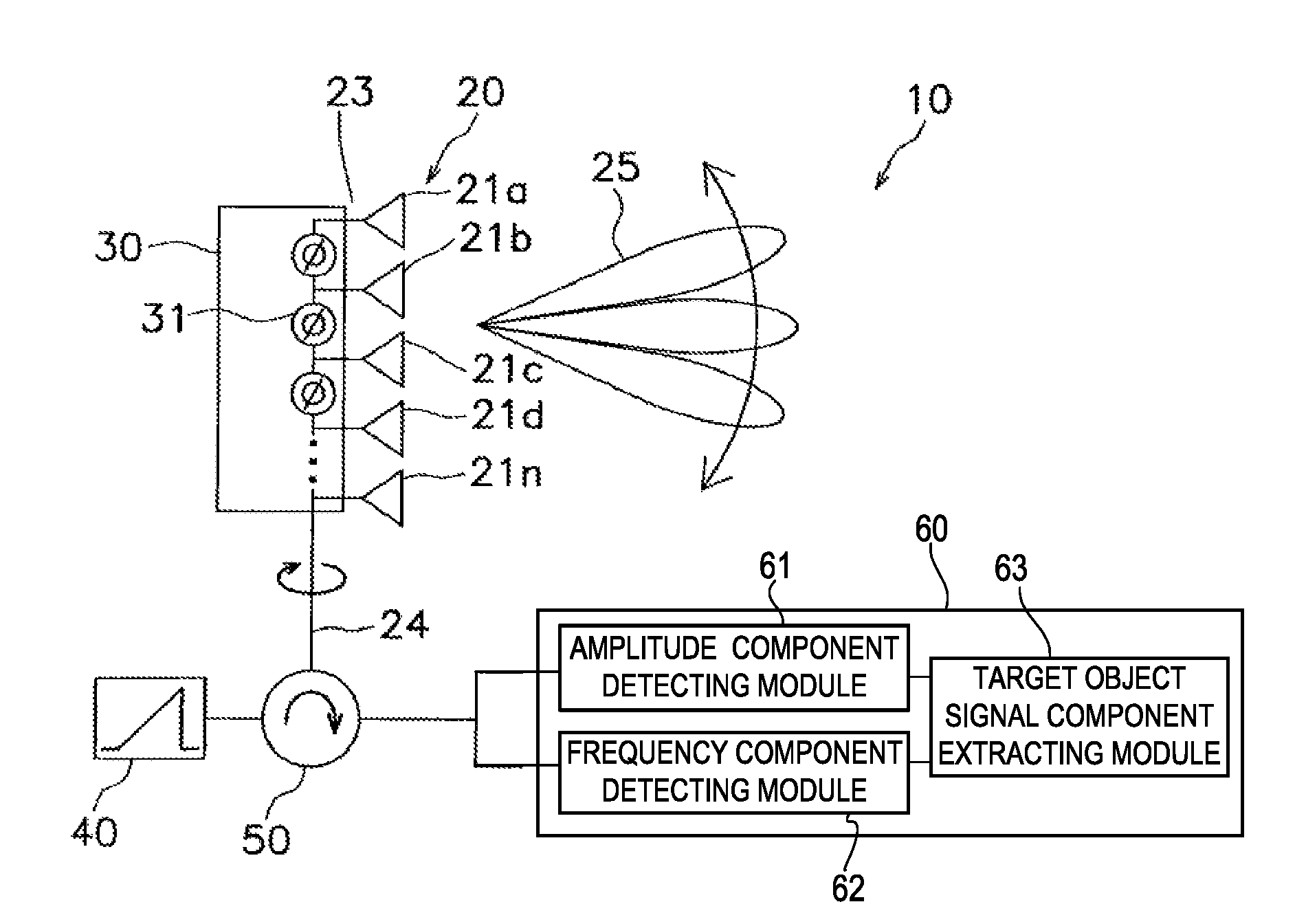
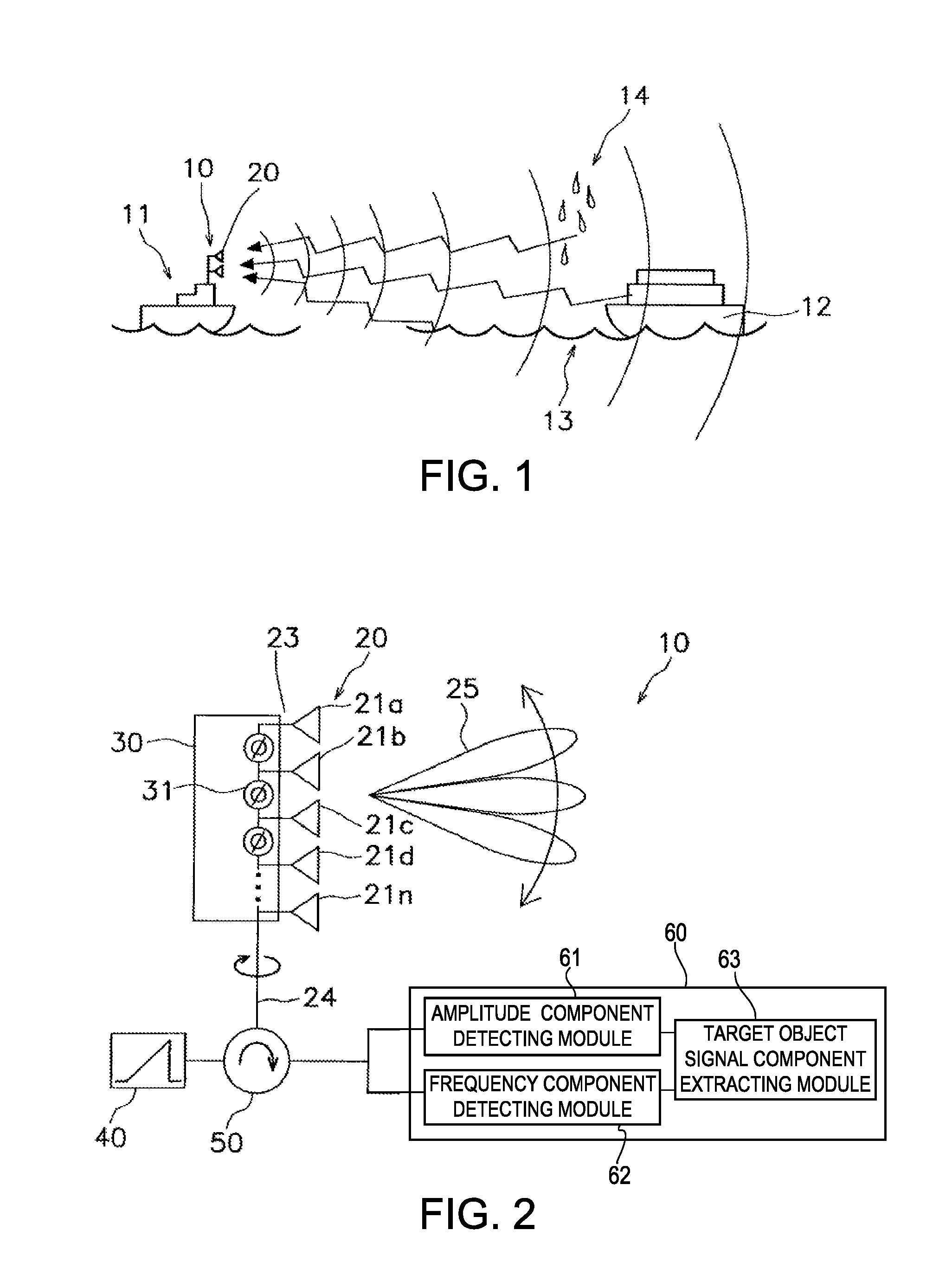
[0043]Hereinafter, a radar apparatus according to a first embodiment of the present invention is described with reference to FIGS. 1 to 17. A ship radar apparatus 10 is provided as an example of using the radar apparatus of the first embodiment. FIG. 1 is a conceptual view explaining a usage example of the ship radar apparatus 10. A ship 11 (hereinafter, referred to as “the ship 11”) in FIG. 1 is mounted with the ship radar apparatus 10. In the ship 11, the ship radar apparatus 10 distinguishes a reflection echo of other ships 12 (target object) among reflection echoes of a sea surface 13, rain 14 and / or fog, for example, to detect the other ships 12.

[0044]Then the detected ship 12 is normally displayed on a display device (not illustrated) including a liquid crystal display. In a radar image to be displayed, a surrounding range of, for example, 360° centered on a position of the radar apparatus (antenna) is displayed, and the origin of the displayed image corresponds to the positio...

modified example 1-1

[0072]The radar apparatus 10 of the above embodiment is configured to detect the target object signal component 71 without considering movement (rolling, pitching) of the ship 11 mounted with the radar apparatus 10. However, when the detection performed for the signal component which is transmitted and received in a state where the ship 11 inclines, the antenna 20 is also inclined and the target object signal component may not be correctly detected from the reception signal. Therefore, a correction of inclination of the ship 11 is preferred to be performed by using, for example, an inclination detecting sensor for detecting an inclined angle of the ship 11. In a modified example described below, a reception module 60A is provided so that the inclined angle of the ship 11 is obtained from the data provided to the target object signal component extracting module 63.

[0073]FIG. 12A shows an area Ar1 of the reception signal when scanning a range of ±10° in the elevation / depression angle ...

modified example 1-2

[0078]As shown in FIG. 13, a radar apparatus 10B according to another modified example of the first embodiment is provided with a reception module 60B having a target object estimating module 65, in addition to the configuration of the radar apparatus 10. The target object estimating module 65 acquires the data from the target object signal component extracting module 63 and estimates whether the acquired data is from a target object. The estimation by the target object estimating module 65 is for estimating the two-dotted chain line DL1 shown in FIG. 12A, that is an envelope curve indicating the sea surface, and estimating whether the data is from the target object based on the envelope curve. The envelope curve can be obtained by, for example, similar to the method in the modified example 1-1, obtaining a difference between the theoretical value and the actual measurement value. The radar apparatus 10B is mounted on the ship 11 shown in FIG. 1 same as the radar apparatuses 10 and ...


PUM


Abstract

This disclosure provides a radar apparatus, which includes an antenna for discharging a transmission beam with frequencies corresponding to elevation / depression angles with respect to a particular surface and receiving a reflection echo from a reflective body and a reception module for detecting an elevation / depression angle of the reflective body based on a frequency component of a reception signal received by the antenna and detecting a distance of the reflective body based on a time component of the reception signal.

Description

CROSS-REFERENCE TO RELATED APPLICATION(S)[0001]The application claims priority under 35 U.S.C. §119 to Japanese Patent Application No. 2010-258864, which was filed on Nov. 19, 2010 the entire disclosure of which is hereby incorporated by reference.TECHNICAL FIELD[0002]The present invention relates to a radar apparatus and a method of detecting a target object in a surrounding area while rotating an antenna, and especially relates to a radar apparatus and a method of detecting a target object that are used in a transportation equipment that moves (rolls, pitches), such as a ship.BACKGROUND OF THE INVENTION[0003]Generally, in radar apparatuses, a electromagnetic wave is discharged and the reflection wave is received, therefore a target object (a ship or a buoy on the sea) is detected. Further, the detected target object is displayed on a display screen. Particularly for such a radar apparatus that is used in a transportation equipment that moves (rolls, pitches), such as a ship, in ma...

Claims


Application Information

Patent Timeline
Patent Type & Authority Patents(United States)
IPC IPC(8): G01S13/42H01Q3/30H01Q3/04
CPCG01S13/428H01Q3/04H01Q3/30
Inventor TAKASHIMA, TETSUYAKASHIWA, TAKUO
Owner FURUNO ELECTRIC CO LTD
Why Eureka
Try Eureka