Automatic drain

a technology of automatic draining and drain valve, which is applied in the direction of steam traps, mechanical equipment, etc., can solve the problems of increasing the length of time required for discharging liquid, forming such holes, orifices, etc., and reducing the size of the automatic drain. , the time required for the compressed air in the piston chamber to flow, and the effect of sufficient length

Active Publication Date: 2018-05-15
KOGANEI
View PDF14 Cites 2 Cited by
  • Summary
  • Abstract
  • Description
  • Claims
  • Application Information

AI Technical Summary

Benefits of technology

[0009]According to Japanese Examined Patent Application Publication No. 45-36182, the float is disposed on top of the servo, and the piston functioning as the partition member and the spring are incorporated in the servo. In this arrangement, the length dimension of the container in which the servo and float are incorporated is large. Miniaturizing an automatic drain including such a long container is, therefore, difficult. Besides, to miniaturize the automatic drain, the capacity of the piston chamber supplied with compressed air from the collection container must be reduced. The length of time required for discharging compressed air of the piston chamber to the outside corresponds to the length of time required for discharging liquid collected in the collection chamber to the outside. It is necessary to set a period of time from start to finish the discharge of almost all the liquid in the collection container. That is, the length of time required for discharging the liquid to the outside increases with increase in capacity of the piston chamber. If the inner diameter of the orifice communicatively connecting the piston chamber to the outside is reduced to lessen the flow rate of compressed air in the orifice, it results in an increase in the length of time required for discharging the liquid. For this reason, when designing the reduced capacity of the piston chamber, the inner diameter of the orifice communicatively connecting the piston chamber to the outside is usually designed to be small.
[0012]An object of the present invention is to provide an automatic drain improved in operation characteristics and reduced in size.
[0013]Another object of the present invention is to further improve the automatic drain in assembling workability.
[0015]The liquid accumulated in the collection container of the automatic drain is discharged through the drain hole provided to the valve seat to the outside. The drain valve which opens and closes the drain hole is integrally provided with the piston. When the level of the accumulated liquid rises, it moves the float up, which causes compressed air in the collection container to be supplied into the piston chamber, in which the piston moves down, thus opening the drain valve. When the compressed air supplied into the piston chamber is discharged out of the bleed channel provided to the drain valve, the piston moves up, closing the drain hole. The length of time required for discharging the liquid through the opened drain hole to the outside corresponds to the length of time required for discharging the compressed air of the bleed channel. By composing the bleed channel from the bleed hole and the orifice pin inserted therein, the bleed channel is formed precisely as a bleed channel with an extremely small channel area. Even if the capacity of the piston chamber is small, therefore, the time required for the compressed air in the piston chamber to flow through the bleed hole to the outside is increased, which means that a liquid discharge time of a sufficient length is achieved. As a result, the size of the automatic drain can be reduced, and at the same time, its operation characteristics can be improved. In such a case, fewer errors are made in machining the drain valve, so that fewer defective automatic drains result. Hence the assembling workability of the automatic drain is improved.

Problems solved by technology

Miniaturizing an automatic drain including such a long container is, therefore, difficult.
If the inner diameter of the orifice communicatively connecting the piston chamber to the outside is reduced to lessen the flow rate of compressed air in the orifice, it results in an increase in the length of time required for discharging the liquid.
Forming such a hole, i.e., orifice, with a small diameter on a resin drain valve formed by injection molding is difficult.
Forming such an orifice by a boring process using a drill is also difficult.
Such an orifice has a small inner diameter and a long, deep hole, and therefore can hardly be made by resin molding using a die or by drilling.
In this case, therefore, manufacturing the drain valve is difficult, which puts limitations on an improvement in the manufacturing yield of the drain valve.
This results in a delay in a returning action to an original state after discharging the collected liquid, thus leading to the deterioration of the operation characteristics of the automatic drain.

Method used


Image

  • Automatic drain
  • Automatic drain
  • Automatic drain

Examples


Embodiment Construction

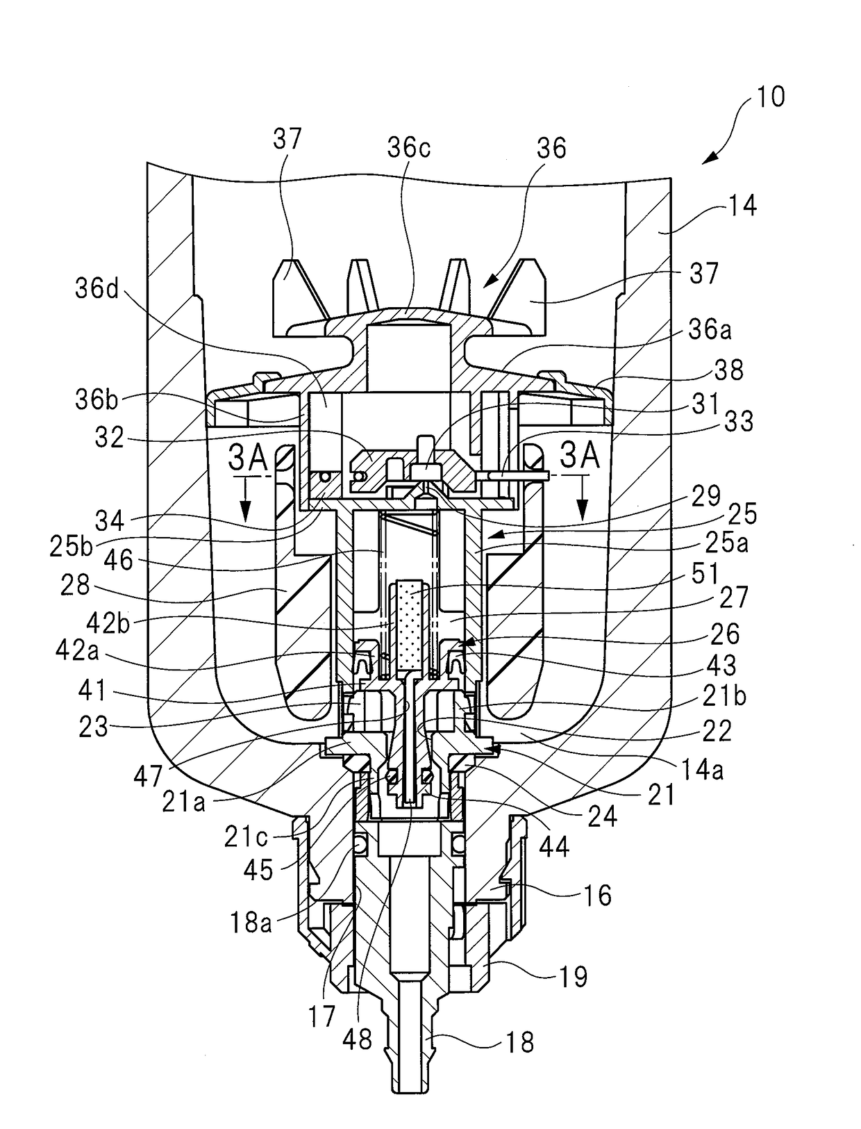
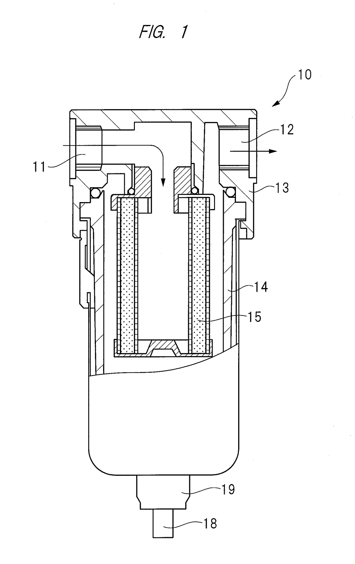
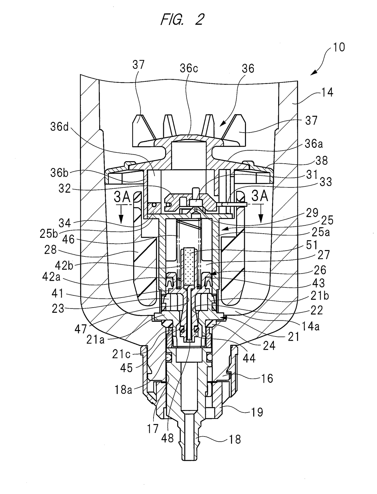
[0028]Hereinafter, embodiments of the present invention will be described in detail with reference to the drawings. As shown in FIG. 1, an automatic drain 10 includes a port block 13 having an inflow port 11 and an outflow port 12 for taking in and discharging compressed air. A collection container 14 is referred also as “bowl” and attached to the port block 13. The port block 13 forms part of the collection container 14, and the inflow port 11 and the outflow port 12 are provided to the upper part of the port block 13. A space disposed below the port block 13, that is, formed in the collection container 14 serves as a separation space. A cylindrical filter element assembly 15 is disposed in the collection container 14, and attached to the port block 13. This automatic drain 10 is incorporated in an air pressure line for supplying compressed air from an air pressure source to pneumatic equipment, a primary pipeline extending from the air pressure source is connected to the inflow po...


PUM


Abstract

A drain hole for connecting a discharge hole and the inside of a collection container to each other is formed in a valve seat member. A float support is provided with a cylinder portion in which a piston is incorporated in a slidable manner. An vent valve for opening and closing a vent hole by means of a float is provided to the float support. A drain valve which operates between a closing position at which the drain valve closes the drain hole and an open position at which the drain valve opens the drain hole is provided to the piston. A bleed channel for connecting a piston chamber and the discharge hole to each other is formed by an orifice pin mounted in a bleed hole provided to the drain valve.

Description

CROSS REFERENCE TO RELATED APPLICATION[0001]This application is entitled to the benefit of and incorporates by reference subject matter disclosed in International Patent Application No. PCT / JP2014 / 080155 filed on Nov. 14, 2014 and Japanese Patent Application No. 2014-083795 filed on Apr. 15, 2014, the contents of all of which are incorporated by reference herein.TECHNICAL FIELD[0002]The present invention relates to an automatic drain (“auto-drain”) which separates and collects foreign matters such as liquid from compressed air, and which automatically discharges collected and accumulated foreign matters to the outside when the amount of accumulated foreign matters reaches a predetermined amount.BACKGROUND ART[0003]An automatic drain for draining a liquid component, such as water and oil, contained in the compressed air is provided to an air pressure line through which compressed air is supplied from an air pressure source to air-supplied components such as pneumatic equipment.[0004]...

Claims


Application Information

Patent Timeline
Patent Type & Authority Patents(United States)
IPC IPC(8): F16T1/20F16T1/22
CPCF16T1/22F16T1/20
Inventor DOKI, MAKOTO
Owner KOGANEI
Why Eureka
Try Eureka