Method of calibrating surface texture measurement device

a measurement device and surface texture technology, applied in the direction of mechanical measurement arrangements, mechanical roughness/irregularity measurements, instruments, etc., can solve the problems of inability to accurately evaluate the thickness of the measured object, the mutual relationship cannot be accurately evaluated between the measurement results provided by the upward stylus, and the measurement thus takes time due, etc., to achieve accurate mutual positional relationship, improve accuracy, and improve accuracy

Active Publication Date: 2015-01-06
MITUTOYO CORP
View PDF10 Cites 3 Cited by
  • Summary
  • Abstract
  • Description
  • Claims
  • Application Information

AI Technical Summary

Benefits of technology

[0010]An advantage of the present invention is to provide a method of calibrating a surface texture measurement device having an upward stylus and a downward stylus, the method providing an accurate mutual positional relationship of the upward stylus and the downward stylus.
[0011]An aspect of the present invention provides a method of calibrating a surface texture measurement device including a detector including a measurement arm supported swingably in a vertical direction at a rotation axis as a support point, an upward stylus and a downward stylus each provided in an end portion of the measurement arm and projecting in a swing direction of the measurement arm, and a detection unit that detects a swing amount of the measurement arm; a stage holding a measured object; and a relative movement mechanism relatively moving the detector and the stage. The method includes obtaining first axis shape measurement data by relatively moving the detector and the stage in a first axis direction while the downward stylus is in contact with an upper surface of a reference sphere to obtain first axis upper shape measurement data and by relatively moving the detector and the stage in the first axis direction while the upward stylus is in contact with a lower surface of the reference sphere to obtain first axis lower shape measurement data; and calculating offset amounts of the upward stylus and the downward stylus based on a first center coordinate obtained from the first axis upper shape measurement data and a second center coordinate obtained from the first axis lower shape measurement data.
[0012]According to the configuration above, in the obtaining of the first axis shape measurement data, the first axis upper shape measurement data is obtained by relatively moving the detector and the stage in the first axis direction while the downward stylus is in contact with the upper surface of the reference sphere. The first axis lower shape measurement data is obtained by relatively moving the detector and the stage in the first axis direction while the upward stylus is in contact with the lower surface of the reference sphere. Then, in the calculating of the offset amounts, the offset amounts of the upward stylus and the downward stylus are calculated based on the first center coordinate obtained from the first axis upper shape measurement data and the second center coordinate obtained from the first axis lower shape measurement data. Thereby, the mutual positional relationship between the upward stylus and the downward stylus can be accurately provided in the first axis direction, thus allowing accurate evaluation of a mutual relationship of measurement results with the upward stylus and measurement results with the downward stylus.
[0013]In the method of calibrating the surface texture measurement device according to the present invention, the obtaining of the first axis shape measurement data may include obtaining a maximum diameter by moving in a second axis direction orthogonal to the first axis direction to obtain a plurality of first axis upper shape measurement data and a plurality of first axis lower shape measurement data and thus to obtain an upper maximum diameter portion of the reference sphere from the plurality of obtained first axis upper shape measurement data as well as to obtain a lower maximum diameter portion of the reference sphere from the plurality of obtained first axis lower shape measurement data.
[0014]The method of calibrating the surface texture measurement device according to the present invention may further include obtaining second axis shape measurement data by relatively moving the detector and the stage in the second axis direction orthogonal to the first axis direction while the downward stylus is in contact with the upper maximum diameter portion of the reference sphere to obtain second axis upper shape measurement data of the reference sphere and by relatively moving the detector and the stage in the second axis direction while the upward stylus is in contact with the lower maximum diameter portion of the reference sphere to obtain second axis lower shape measurement data. The calculating of the offset amounts may calculate the offset amounts of the upward stylus and the downward stylus based on the first center coordinate and the second center coordinate, as well as a third center coordinate obtained from the second axis upper shape measurement data and a fourth center coordinate obtained from the second axis lower shape measurement data.
[0015]It is preferred that the method of calibrating the surface texture measurement device of the present invention include setting correction parameters to obtain optimum correction parameters for correction of a measurement error included in the second axis upper shape measurement data and the second axis lower shape measurement data. The setting of correction parameters simultaneously obtains correction parameters for each of a plurality of areas of a measurement range divided along the swing direction of the measurement arm. In such a configuration, the correction parameters are simultaneously estimated for each of the plurality of the areas divided along the swing direction of the measurement arm. The measurement data measured by the styluses (measurement arm) that perform a swing motion can thus be corrected with higher precision.

Problems solved by technology

Measurement thus takes time due to removal and attachment of the aim.
With the surface texture measurement device above having the upward stylus and the downward stylus, however, the mutual relationship cannot be accurately evaluated between the measurement results provided by the upward stylus and the measurement results provided by the downward stylus unless the mutual positional relationship of the upward stylus and the downward stylus is accurately known.
Unless the mutual positional relationship of the upward stylus and the downward stylus is accurately known, the thickness of the measured object cannot be accurately evaluated.

Method used


Image

  • Method of calibrating surface texture measurement device
  • Method of calibrating surface texture measurement device
  • Method of calibrating surface texture measurement device

Examples


first embodiment

[0031](Explanation of Surface Texture Measurement Device)

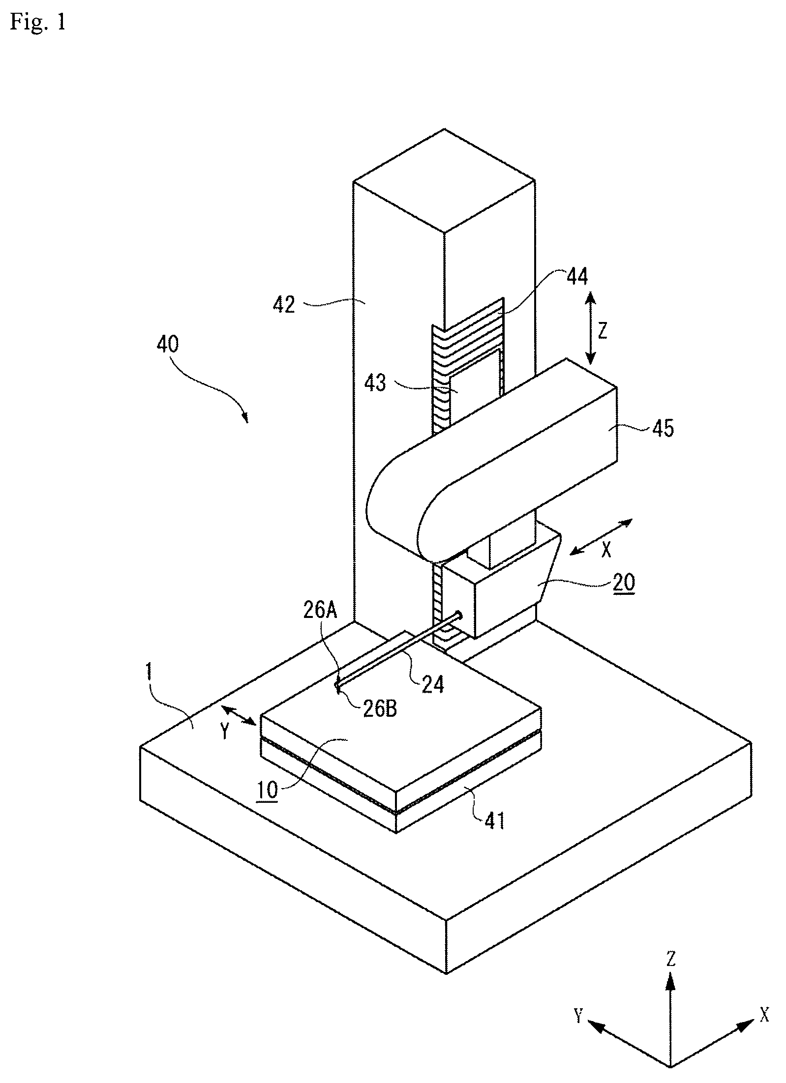
[0032]With reference to FIG. 1, a surface texture measurement device according to the present embodiment has a base 1; a stage 10 placed on the base 1 such that a measured object is placed on an upper surface thereof; a stylus displacement detector 20 having styluses 26A and 26B that come into contact with a surface of the measured object; and a relative movement mechanism (also referred to as a relative movement driver) 40 relatively moving the stylus displacement detector 20 and the stage 10.

[0033]The relative movement mechanism 40 has a Y-axis drive mechanism 41 provided between the base 1 and the stage 10 and moving the stage 10 to one direction of a horizontal direction (Y-axis direction); a column 42 standing on the upper surface of the base 1; a Z slider 43 provided to the column 42 movably in a vertical direction (Z-axis direction); a Z-axis drive mechanism 44 moving up and down the Z slider 43; and an X-axis drive mec...

second embodiment

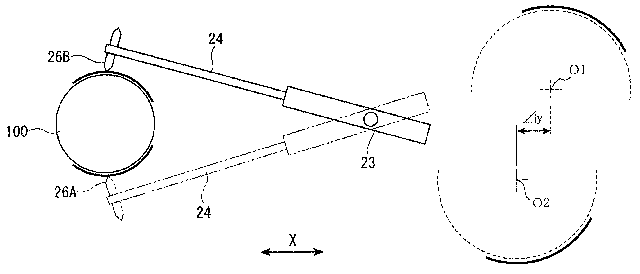
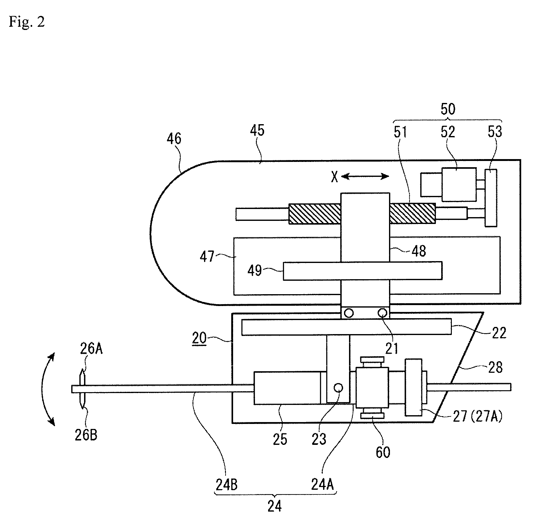
[0048]In the structure of the surface texture measurement device explained in the first embodiment, the measurement arm 24 performs a swing motion (arc motion) in the vertical direction at the rotation axis 23 as a support point, thus causing a measurement error. As shown in FIG. 8, for instance, the measurement data (xm, zm) provided by the downward stylus 26B is different from a correct measurement position (xr, zr) due to an effect of the arc motion of the measurement arm 24. For high-precision measurement, the measurement data (xm, zm) should be appropriately corrected. In the second embodiment, a correction mechanism is provided to correct a measurement error caused by the arc motion of the measurement arm 24. Although the correction mechanism is explained in detail in Japanese Patent Laid-open Publication No. 2007-316046 filed by the Applicant of the present invention, an overview of the same is briefly described here. In the explanation below, a mechanism that includes the X-...


PUM


Abstract

A method of calibrating a surface texture measurement device includes obtaining Y-axis shape measurement data and a maximum diameter portion to obtain upper and lower maximum diameter portions of a reference sphere from Y-axis upper and lower shape data obtained by relatively moving in the Y-axis direction while a downward and an upward styluses are in contact with an upper and a lower surfaces, respectively, of the reference sphere; obtaining X-axis shape measurement data to obtain X-axis upper and lower shape data of the reference sphere by relatively moving in the X-axis direction while the downward stylus is in contact with the upper diameter portion and the upward stylus with the lower diameter portion of the reference sphere; and calculating offset amounts Δx and Δz of the upward and downward styluses from center coordinates O3 and O4 obtained from the shape data.

Description

CROSS-REFERENCE TO RELATED APPLICATIONS[0001]The present application claims priority under 35 U.S.C. §119 of Japanese Application Nos. 2011-060995 and 2012-010453 filed on Mar. 18, 2011, and Jan. 20, 2012, respectively, the disclosures of which are expressly incorporated by reference herein in their entireties.BACKGROUND OF THE INVENTION[0002]1. Field of the Invention[0003]The present invention relates to a method of calibrating a surface texture measurement device. Specifically, the present invention relates to a method of calibrating a surface texture measurement device that measures the shape, roughness, and the like of a measured object by tracing the surface thereof with a stylus.[0004]2. Description of Related Art[0005]A surface texture measurement device is known that moves a stylus along a surface of a measured object in a state where the stylus is in contact with the surface of the measured object, detects a displacement of the stylus caused by the surface shape and surface...

Claims


Application Information

Patent Timeline
Patent Type & Authority Patents(United States)
IPC IPC(8): G01B7/34G01B5/20G01B5/28G01B21/04
CPCG01B21/042G01B5/28G01B5/201
Inventor OMORI, YOSHIYUKIMIKI, SHOUSEI
Owner MITUTOYO CORP
Why Eureka
Try Eureka