
Adjustable occupancy sensor and method of attaching an occupancy sensor to a light fixture

Active Publication Date: 2015-01-06
SCHNEIDER ELECTRIC USA INC
View PDF61 Cites 5 Cited by
  • Summary
  • Abstract
  • Description
  • Claims
  • Application Information

AI Technical Summary

Benefits of technology

This patent describes an adjustable occupancy sensor that can be easily installed on a variety of light fixtures. The sensor is designed to be mounted directly without the need for an adapter, and it can accommodate different offsets to the fixture. Additionally, the sensor has a protective shield to shield the components within the housing. This makes it easy to install and adjust the sensor as needed.

Problems solved by technology

Existing occupancy sensors for light fixtures, such as fluorescent high bay fixtures, are typically incapable of mounting on the fixtures without a special adapter.
As mentioned above, one solution is to offer a special adapter, which adds cost and complexity to the installation of the occupancy sensor.
However, installers of such occupancy sensors often do not anticipate needing an adapter at the time in which the light fixture is installed.

Method used


Image

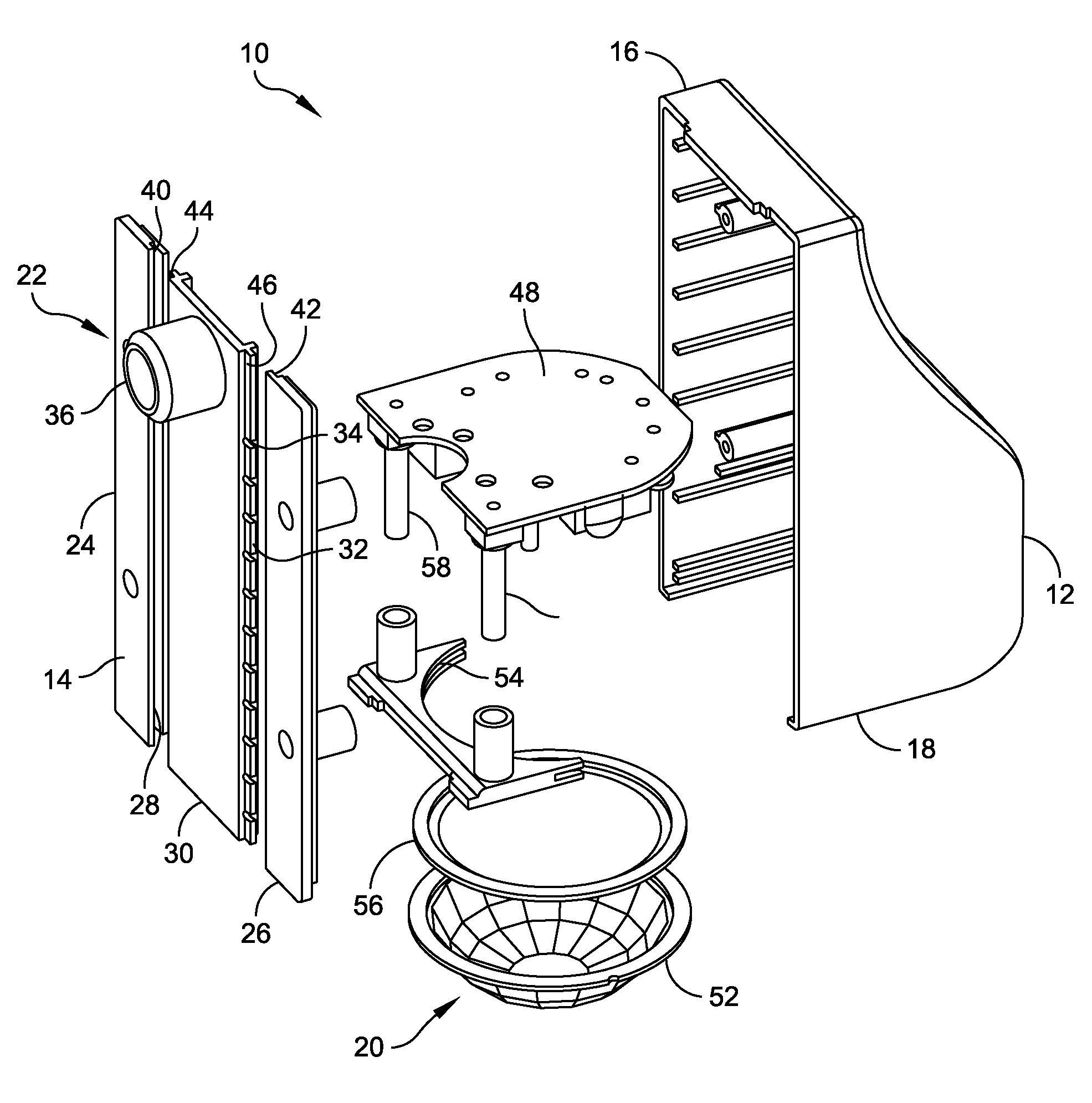
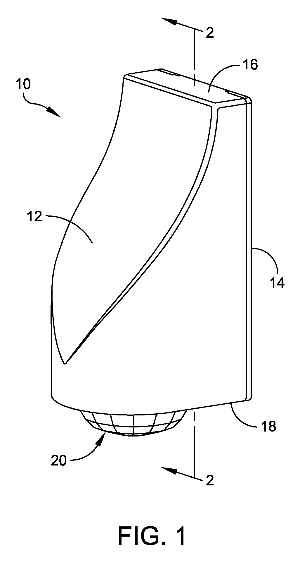
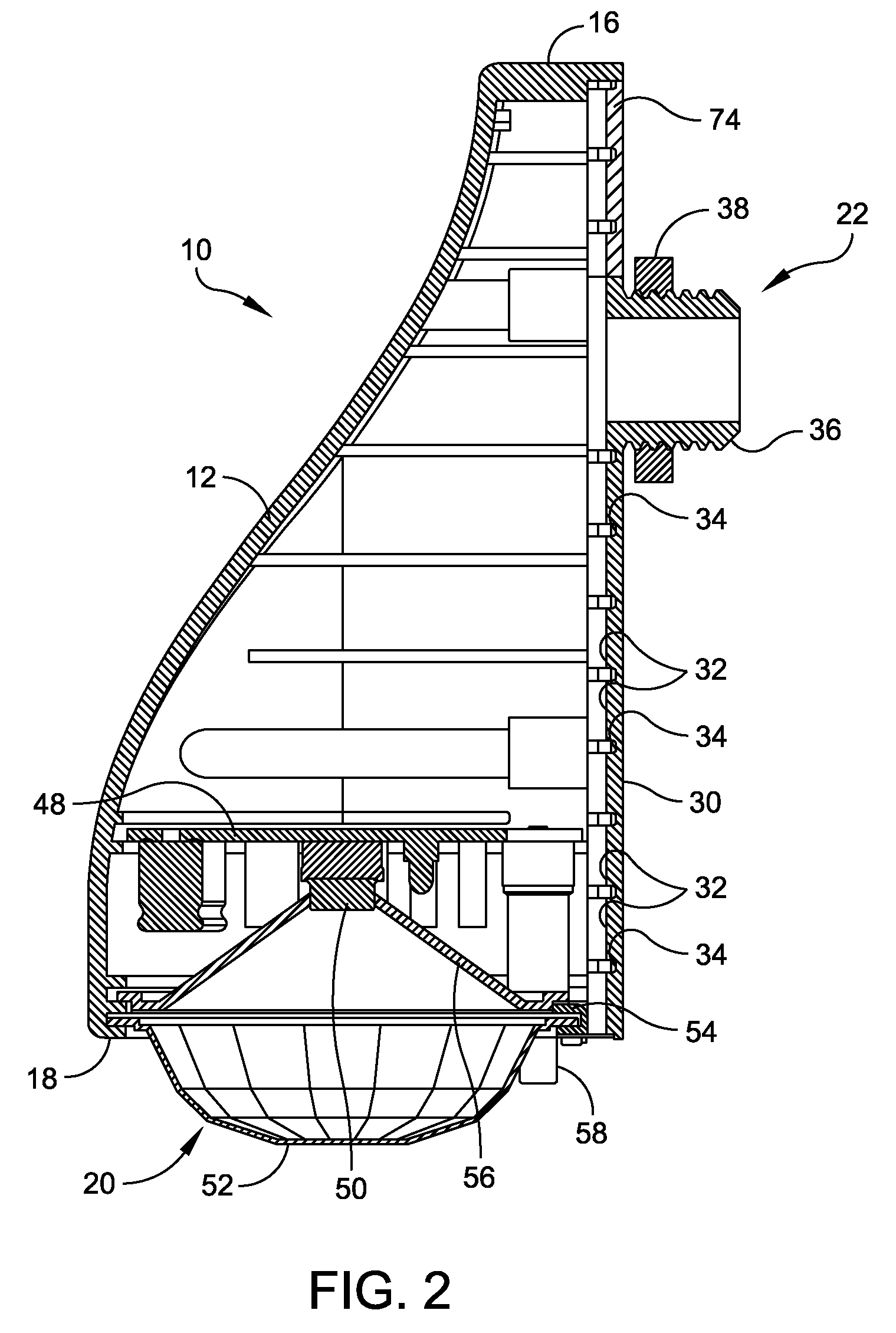
  • Adjustable occupancy sensor and method of attaching an occupancy sensor to a light fixture
  • Adjustable occupancy sensor and method of attaching an occupancy sensor to a light fixture
  • Adjustable occupancy sensor and method of attaching an occupancy sensor to a light fixture

Examples


Embodiment Construction

[0027]For the purposes of illustration only, and not to limit the generality, the present disclosure will now be described in detail with reference to the accompanying figures. This disclosure is not limited in its application to the details of construction and the arrangement of components set forth in the following description or illustrated in the drawings. The disclosure is capable of other embodiments and of being practiced or being carried out in various ways. Also the phraseology and terminology used herein is for the purpose of description and should not be regarded as limiting. The use of “including,”“comprising,”“having,”“containing,”“involving,” and variations thereof herein, is meant to encompass the items listed thereafter and equivalents thereof as well as additional items.

[0028]The present disclosure is directed to an adjustable occupancy sensor assembly that is provided to detect the presence of a person in a room. Embodiments of the adjustable occupancy sensor assem...


PUM


Abstract

An adjustable occupancy sensor capable of being secured to a light fixture includes a housing having a side and a bottom, a sensor assembly attached to the housing at the bottom of the housing, and an adjustable mounting assembly provided on the side of the housing. The adjustable mounting assembly includes a slot defined in the side of the housing and a track having a plurality of segments extending along the length of the track. The track is configured to be releasably secured to the side of the housing within the slot, the plurality of segments being configured to be breakable from the track to adjust a length of the track. The adjustable mounting assembly further includes a connector molded or otherwise secured to the track to connect the housing of the adjustable occupancy sensor to the light fixture. Other embodiments and methods are disclosed herein.

Description

BACKGROUND OF THE INVENTION[0001]1. Field of the Disclosure[0002]The present disclosure relates to lighting assemblies in general, and more particularly to an adjustable occupancy sensor assembly capable of being secured to a light fixture.[0003]2. Discussion of Related Art[0004]High bay occupancy sensors are designed to control lighting in high mount areas. The occupancy sensors turn lamps of a light fixture on and off based on the occupancy of the space. Such occupancy sensors are configured to detect motion directly below the light fixture and at slant angles from vertical up to 45°. Existing occupancy sensors for light fixtures, such as fluorescent high bay fixtures, are typically incapable of mounting on the fixtures without a special adapter. Specifically, a typical occupancy sensor includes a housing that may be fabricated from molded plastic and a ½-inch NPT (“National Pipe Thread”) mounting connector that extends laterally from the housing. The threaded mounting connector i...

Claims


Application Information

Patent Timeline
IPC IPC(8): G08B23/00F21V23/04G08B17/10
CPCF21V23/0471G08B17/10G08B17/113
Inventor DYER, JOHN W.OLSON, JAMES V.
Owner SCHNEIDER ELECTRIC USA INC
Learn More