Sink flange assembly installation method and tool

a technology of sink flange and installation method, which is applied in the direction of metal-working hand tools, metal-working tools, pliers, etc., can solve the problems of affecting the installation process, and requiring more time and effort, so as to avoid injury to the fingers and thumbs of the installer, the installation process proceeds quickly and efficiently

Inactive Publication Date: 2005-11-15
RAMIREZ ALBERT F
View PDF22 Cites 4 Cited by
  • Summary
  • Abstract
  • Description
  • Claims
  • Application Information

AI Technical Summary

Benefits of technology

[0008]This invention addresses the concerns outlined above by providing a facilitating method and tool for installing a locking ring on the sink flange component of a sink flange assembly. The tool is used to engage the locking ring, to spread the locking ring, and to place the locking ring in the groove without disrupting the sink flange seating. Doing so according to the present invention avoids the need for two people or for a heavy weight on the sink flange. Installation proceeds quickly and efficiently without lost time, and it avoids injury to the fingers and thumb of the installer.

Problems solved by technology

As he does so, certain problems arise.
In doing this, various problems arise.
First, the sink flange tends to move upwardly when any upward pressure is applied to it, and that dislodges the sink flange from its seated position on the plumber's putty.
Either way involves more time and effort.
Many missed attempts often result, jarring the sink flange all the more.
Another method of installing the locking ring attempts to spread the locking ring by hand while pushing it upwardly, risking finger and thumb cuts on the sharp edge of the sink flange.
In other words, existing procedures are time consuming and frustrating and they risk injury.
These methods also present the hazard of the backup ring and the mounting ring falling down on the installer's face or head while he is working below the sink.

Method used


Image

  • Sink flange assembly installation method and tool
  • Sink flange assembly installation method and tool
  • Sink flange assembly installation method and tool

Examples


Embodiment Construction

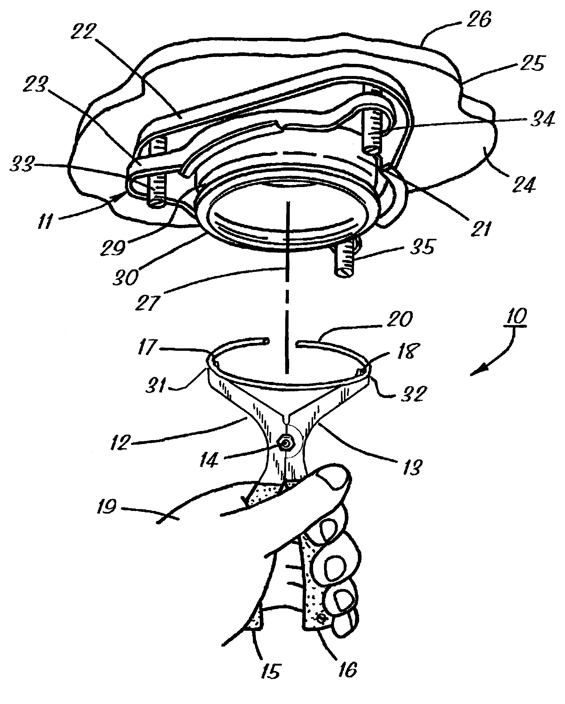
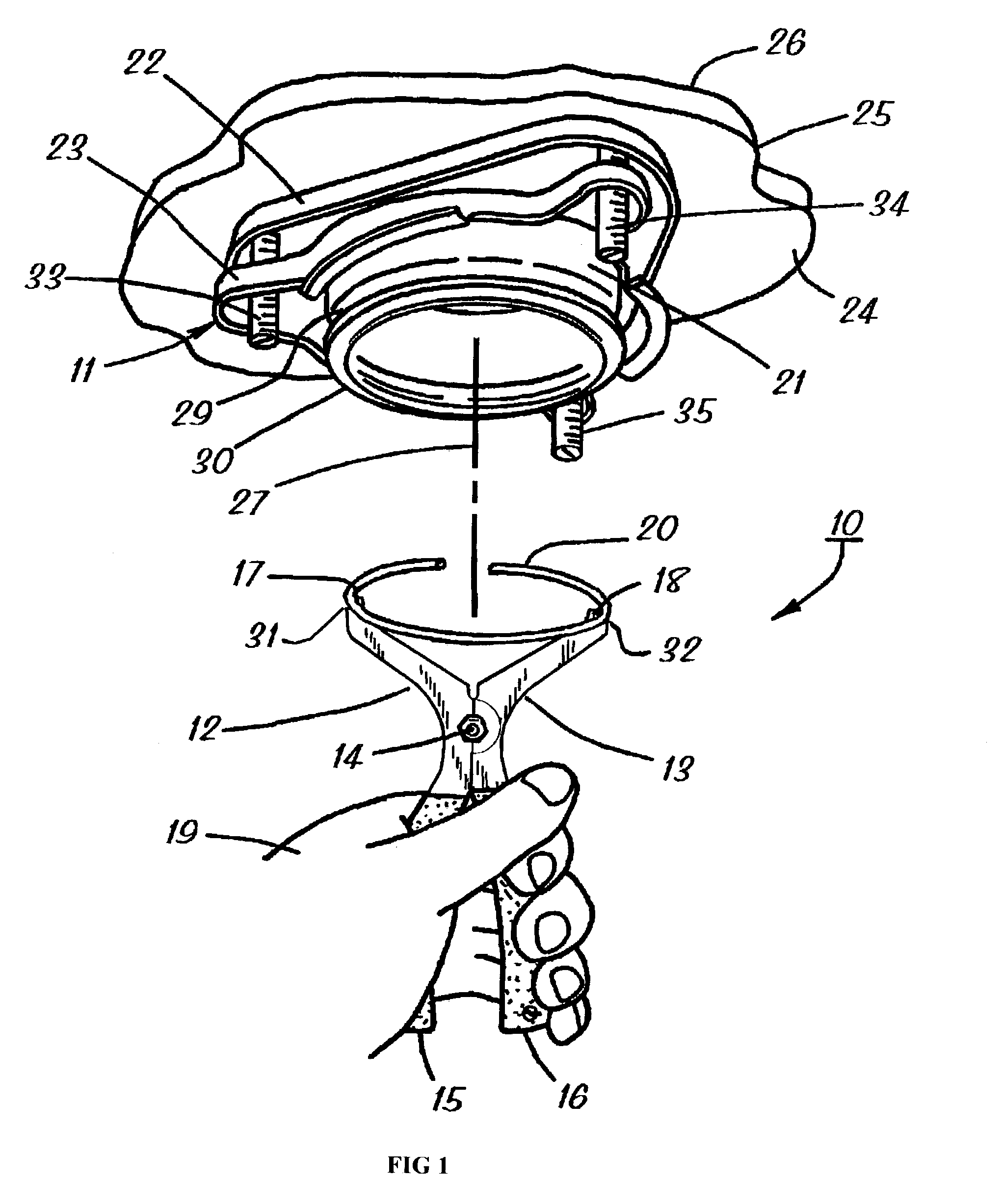
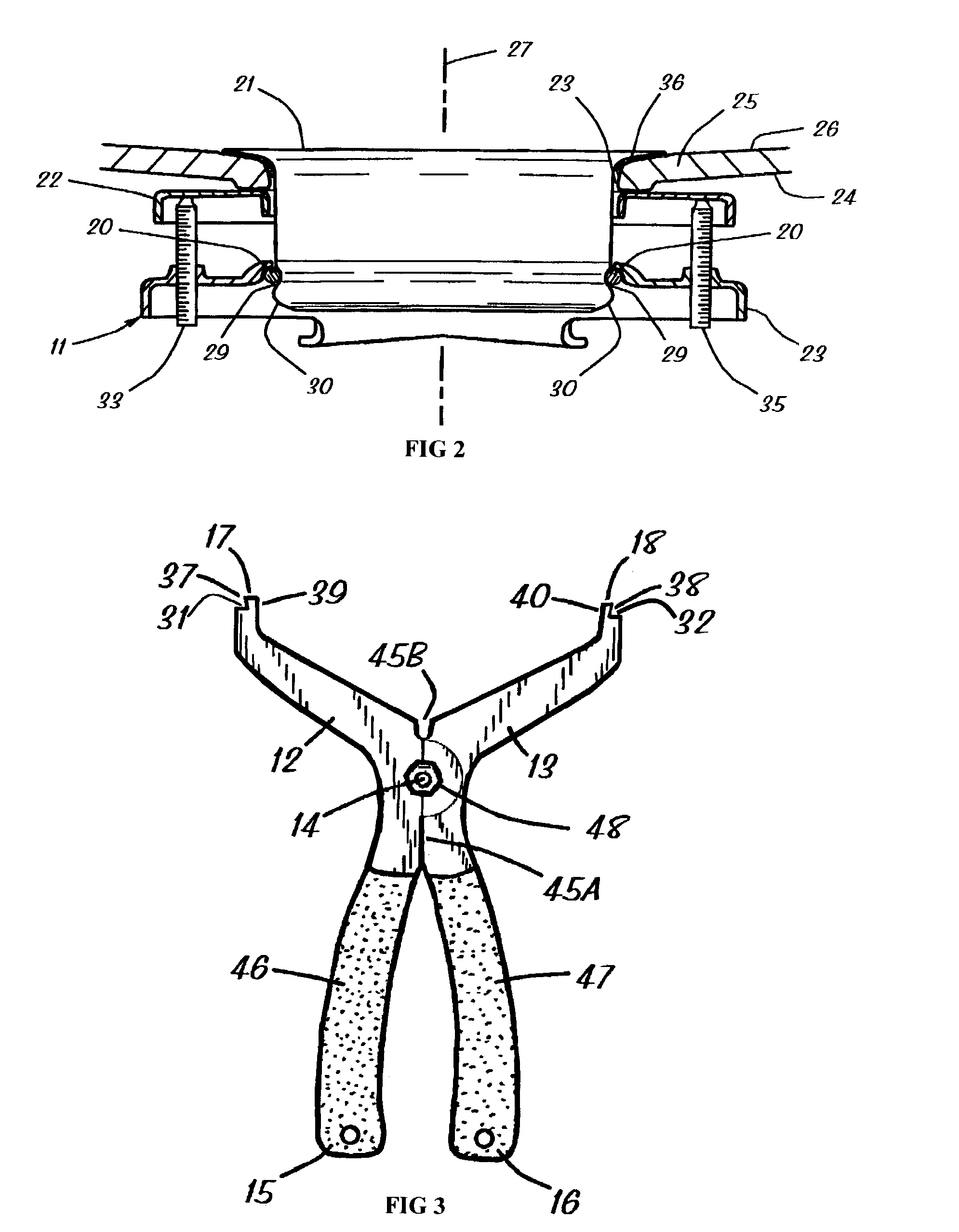
[0017]FIGS. 1–5 of the drawings show various aspects of a method and tool 10 for installing a garbage disposer sink flange assembly 11 according to the invention. Generally, a tool constructed according to the invention includes a pair of first and second elongated members that are pivotally connected to each other at a pivot point to form a pair of opposed first and second handles and a pair of opposed ring-engaging first and second tips such that the first and second tips move away from each other by operation of a person squeezing the first and second handles toward each other. Thus, the tool 10 includes a pair of first and second elongated members 12 and 13 (FIGS. 1 and 3) that are pivotally connected to each other at a pivot point 14 (i.e., a pivotal axis that is generally perpendicular to the page on which FIG. 3 appears) to form a pair of opposed first and second handles 15 and 16 (the proximal end portions of the elongated members), and a pair of opposed ring-engaging first ...


PUM

PropertyMeasurementUnit
sizeaaaaaaaaaa
sizeaaaaaaaaaa
shapeaaaaaaaaaa

Abstract

A tool for installing a locking ring in an annular groove defined by a lower annular rim portion of a sink flange of a garbage disposer sink flange assembly. The tool includes a pair of elongated members that are pivotally connected at a pivot point to form a pair of opposed handles and a pair of opposed ring-engaging tips. The tips define a pair of outwardly facing indentations that adapt the tips to engaging the locking ring in order to spread the locking ring by operation of the person squeezing the handles toward each other. Mechanical stops are located in the opposing handles that prevent excessive spreading of the locking ring. In addition, the tool is configured such that when the tool is brought into position, and the tool is leaned over the locking ring is released from the ring-engaging tips.

Description

[0001]This application is a continuation in part (CIP) and claims the benefit of U.S. Utility application Ser. No. 09 / 961,851 filed Sep. 24, 2001 now U.S. Pat. No. 6,615,474 which claims the benefit of U.S. Provisional Application Ser. No. 60 / 281,084 filed Apr. 2, 2001.FIELD OF THE INVENTION[0002]This invention relates generally to home construction equipment and tools, and more particularly to a method and tool for installing a sink flange assembly of the type having a locking ring component that fits in an annular groove on a sink flange component (e.g., a typical garbage disposer sink flange assembly).BACKGROUND OF THE INVENTION[0003]The term “garbage disposer sink flange assembly” refers to an assembly that fits in the drain hole of a sink for use in mounting a food waste disposer unit (i.e., a garbage disposer) just beneath the sink. Regardless of the particular type and kind, the garbage disposer sink flange assembly serves as means to provide a watertight mounting on the sink...

Claims


Application Information

Patent Timeline
Patent Type & Authority Patents(United States)
IPC IPC(8): B25B27/14B25B27/20
CPCB25B27/20B25B27/205Y10T29/5363Y10T29/4987Y10T29/539
Inventor RAMIREZ, ALBERT F.
Owner RAMIREZ ALBERT F
Why Eureka
Try Eureka