
Portable hose cutoff saw with biasing pins

a hose and biasing pin technology, applied in the field of portable saws, can solve the problems of insufficient tension in the hose for providing a straight cut, inconvenient portability, and inefficient prior art circular saws for cutting hoses

Inactive Publication Date: 2015-01-13
THE GATES CORP
View PDF5 Cites 0 Cited by
  • Summary
  • Abstract
  • Description
  • Claims
  • Application Information

AI Technical Summary

Benefits of technology

[0006]In view of the above deficiencies in the prior art, it is an object of the present invention to provide a portable hose cutoff saw having a novel base structure such that the saw is stable without having to bolt or otherwise secure the saw to a planar surface. It is a further object of the present invention to provide a portable hose cutoff saw having a plurality of slideably adjustable hose biasing pins that may be adjusted to optimally bias the hose at or about a portion of a hose to be cut by the saw, thereby resulting in a consistent and straight cut of the hose.
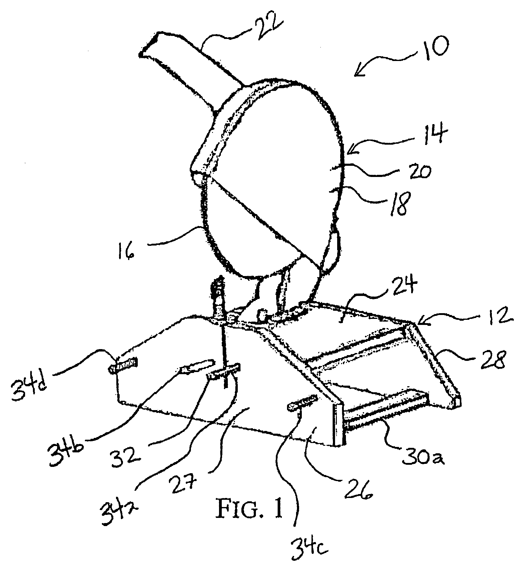
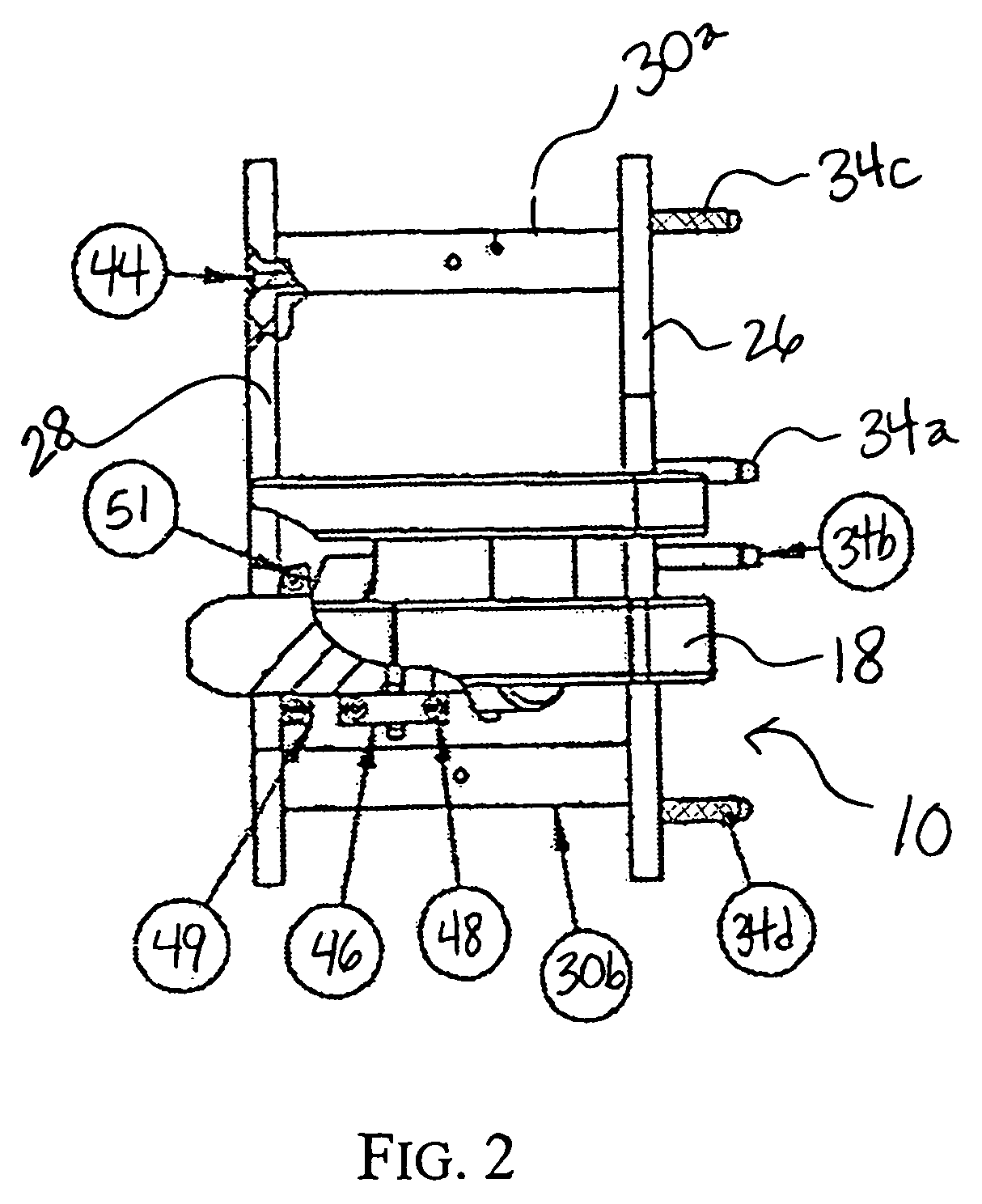
[0009]In another aspect of the present invention, there is provided portable hose cutoff saw having a plurality of slideably adjustable hose biasing pins that may be adjusted to optimally bias the hose at or about a portion of a hose to be cut by the saw, thereby resulting in a consistent and straight cut of the hose. The saw comprises a base including a front plate, and a main body having a saw blade and a handle, the main body pivotally mounted on the base, and a plurality of slideably adjustable pins mounted on a front face of the front plate around and / or under which the hose is snaked.
[0012]Preferably, the pins are mounted on the front face of the front plate such that each of the pins is slidable and / or movable in at least one of a horizontal or vertical direction, i.e. up, down, left and / or right, or therebetween, to optimally bias the hose at or about the location of the hose to be cut without the need to remove and reconnect any of the biasing pins. The pins may be mounted such that they may be selectively engaged, disengaged, and slideably adjusted on the front face of the front plate without the need to remove the pin from the front face. For example, the pins may include a spring, slot, and / or screw structure, or any other suitable structure known in the art that allows the pin to be adjusted in a horizontal or vertical direction, or therebetween, by a desired increment without removing the pin from the front face. Once the hose is coiled around and / or under the first and second biasing pins, the saw blade can be lowered with respect to the base to efficiently and evenly cut the hose in front of the cutting recess, and typically between a pair of the first biasing pins. The saw can be manual or preferably power generated with battery or AC power.

Problems solved by technology

As such, prior art circular saws for cutting a hose are often inefficient and have limited portability.
However, when the main body, including the saw blade, is lowered relative to the base to cut the hose in such saws, there may be insufficient tension in the hose to provide a straight cut.
The user then has to repeat the cut, is left with an undesirable cut piece of hose, or alternatively must use another cutting device to finish the cut.
This may result in a substantial loss of materials, time, and other resources, particularly when cutting a bulk quantity of hose pieces.
One of the main sources of the insufficient tension in the hose to be cut in such prior art saws is the lack of adjustability of the pins or other hose supporting structure.
However, changing the location of the pins in this way in inefficient and time-consuming, particularly when cutting a large number of different sized pieces of hose, and does not at all allow for much smaller incremental changes in the position of the pins.
Further, such pins can often be dislodged by the operation of the saw, such as by vibrations, thereby requiring more time to repeatedly check the connection of the pins, and reconnect the pins to the front wall of the saw if necessary.

Method used


Image

  • Portable hose cutoff saw with biasing pins
  • Portable hose cutoff saw with biasing pins
  • Portable hose cutoff saw with biasing pins

Examples


Embodiment Construction

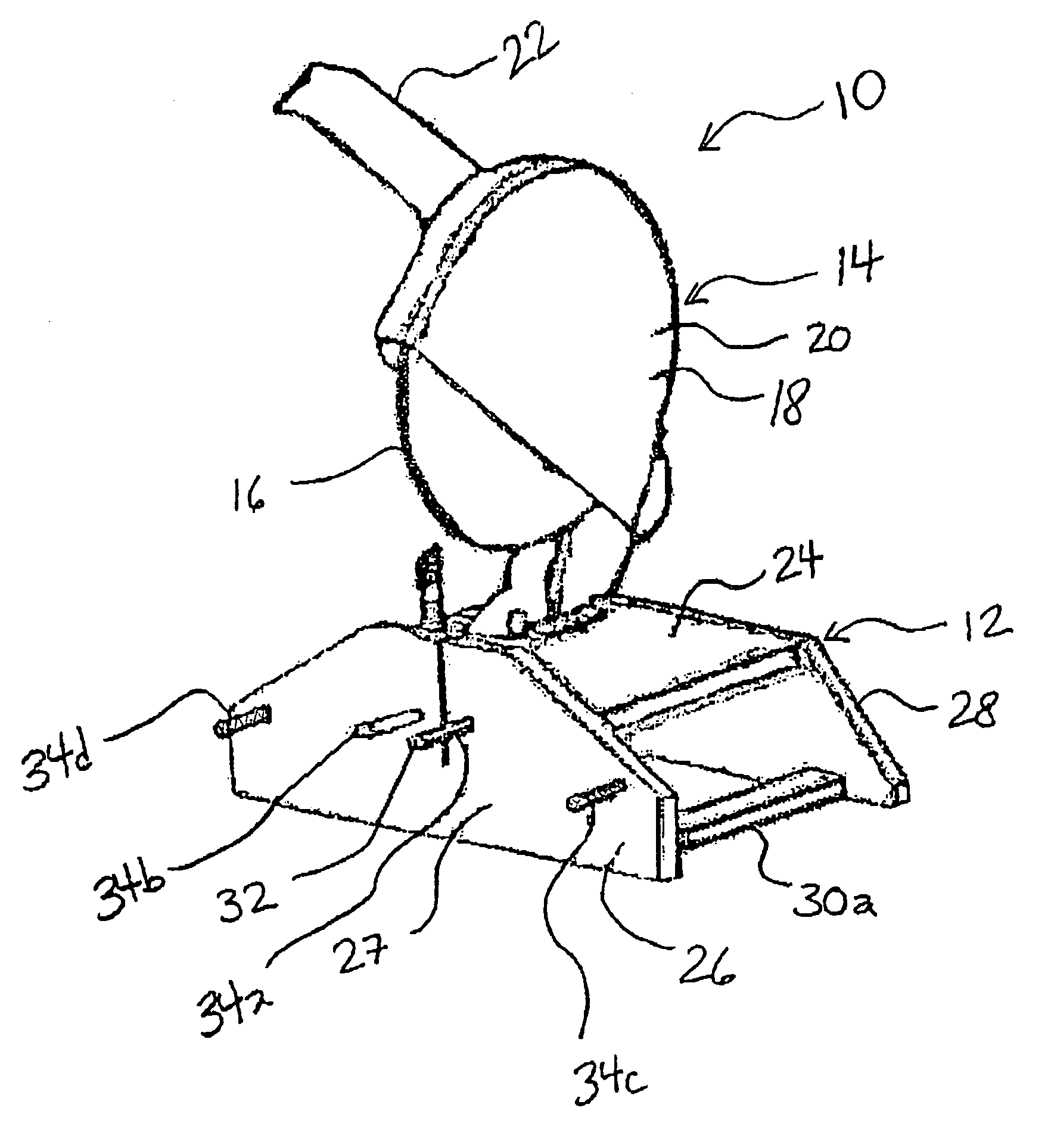
[0019]Now referring to the figures, as shown in FIG. 1, the circular saw 10 includes a base 12 and a saw body 14 mounted on the base. Saw body 14 includes a circular or disc-shaped blade 16 disposed generally on one side of saw body 14 and a housing 18. In one embodiment, housing 18 encases a motor (not shown), which drives the blade 16. Any suitable power source known in the art may be utilized to power the motor, such as, for example, such as a battery or AC power source. Typically, saw 10 includes a power cord (not shown) for delivering power to the motor. Saw body 14 preferably includes an upper blade guard 20 for preventing injury and for covering the upper portion of blade 16, and a handle 22 extending outward from saw body 14. The user may lower main body 14 and saw blade 16 by grasping handle 22 and pushing the handle downward with respect to base 12 to cut hose as will be discussed in detail below.

[0020]By the term “hose” as used herein, it is meant any hose, flexible pipe,...


PUM

PropertyMeasurementUnit
diameteraaaaaaaaaa
total lengthaaaaaaaaaa

Abstract

The present invention is directed to a portable hose cutoff saw having an improved stable base structure comprising a front plate and a back plate, a top plate extending transversely between the front and back plates interconnecting said front and back plates, and at least one connecting member extending transversely between a bottom portion of the front and back plates. The present invention also provides for a portable hose cutoff saw having a plurality of slideably adjustable hose biasing pins that may be adjusted to optimally bias the hose at or about a portion of a hose to be cut by the saw, thereby resulting in a consistent and straight cut of the hose.

Description

FIELD OF THE INVENTION[0001]The invention relates to a portable saw, and more particularly to a portable hose cutoff saw having a novel base structure for improved stability and portability. The invention also relates to a portable hose cutoff saw having a plurality of slideably adjustable hose biasing pins that may be adjusted to optimally bias the hose at or about a portion of a hose to be cut by the saw, thereby resulting in a consistent and straight cut of the hose.BACKGROUND OF THE INVENTION[0002]Circular saws for cutting a hose are generally known in the art. Typically, such saws have a base and a main body, including a motor and a circular saw blade, mounted on the base. The saw blade is coupled to and driven by the motor for cutting a piece of hose positioned in the blade's pathway. Due to the substantial weight of the motor and saw blade relative to the weight of the base, most known circular saws must be bolted or otherwise secured to a table or planar surface when in use ...

Claims


Application Information

Patent Timeline
Patent Type & Authority Patents(United States)
IPC IPC(8): B26D7/01B23D45/04B23D45/12B23D47/02B23D47/04
CPCB23D45/042B23D45/12B23D47/025B23D47/04Y10T83/748Y10T83/7587Y10T83/8773
Inventor BAUER, MARTIN K.AUSTIN, STEVEN G.
Owner THE GATES CORP
Learn More