
Semiconductor device for applying well bias and method of fabricating the same

a semiconductor and well bias technology, applied in semiconductor devices, semiconductor/solid-state device details, electrical apparatus, etc., can solve the problems of nmos transistors spaced apart therefrom, nmos transistors being vulnerable to latch-up phenomena, and affecting the electrical characteristic of nmos transistors, etc., to achieve good bias, reduce chip area, and high integration

Inactive Publication Date: 2006-05-09
SAMSUNG ELECTRONICS CO LTD
View PDF4 Cites 0 Cited by
  • Summary
  • Abstract
  • Description
  • Claims
  • Application Information

AI Technical Summary

Benefits of technology

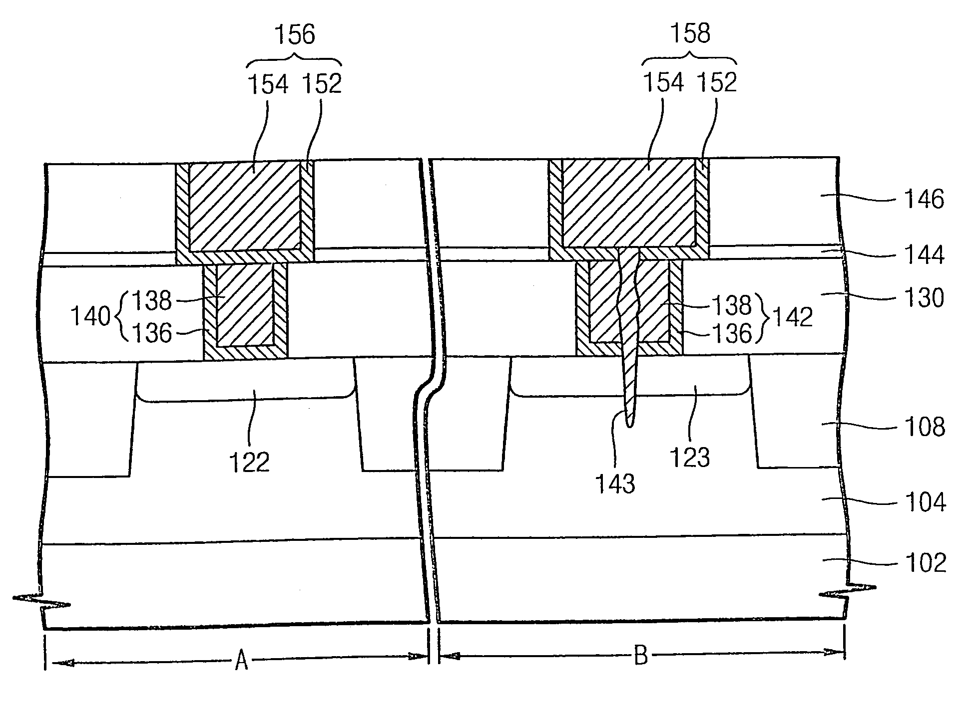
[0013]Embodiments of the present invention provide a semiconductor device where a chip area is reduced to achieve a high integration and a well bias is efficiently applied to a MOS transistor to enhance an electrical characteristic, and methods of fabricating the same.

Problems solved by technology

At the present time, advances in VLSI memories leads to considerable power consumption in NMOS devices.
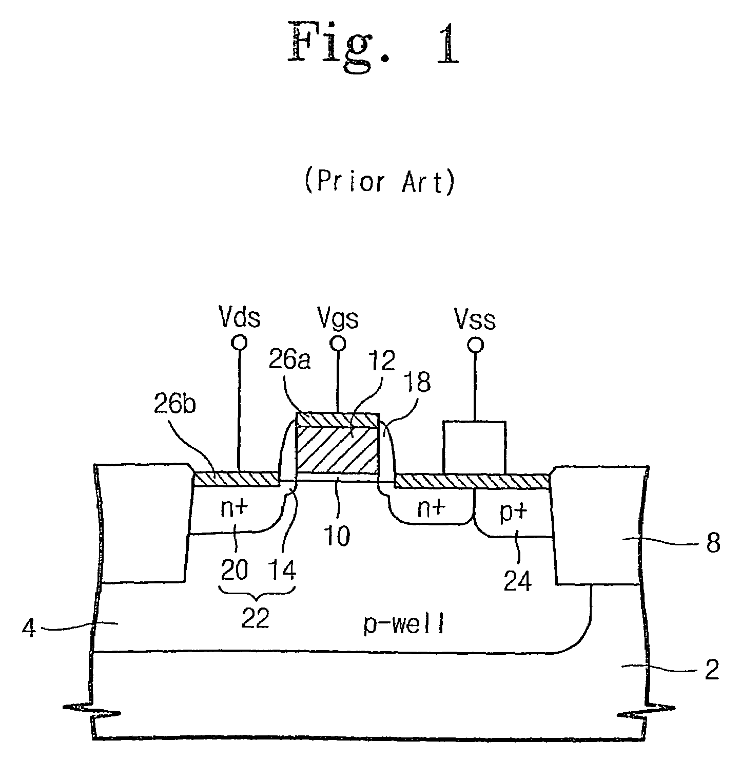
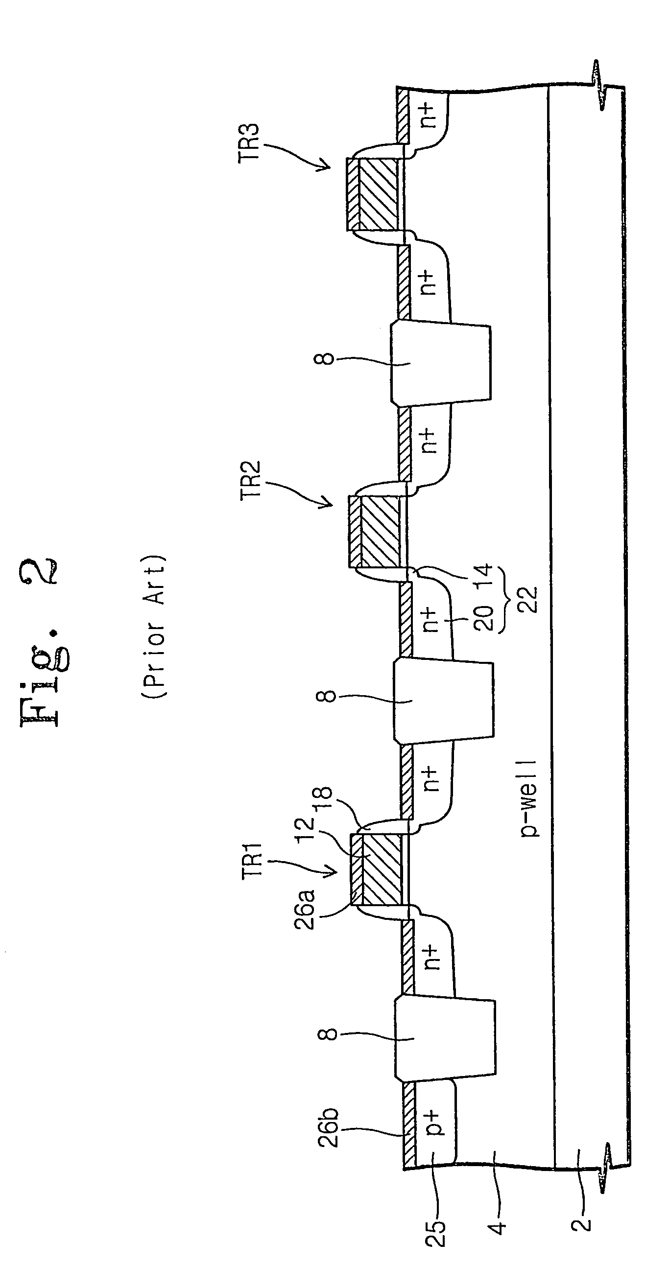
However, the common well pickup region causes an NMOS transistor spaced apart therefrom to be vulnerable to a latch-up phenomenon because the well resistance increases in proportion to the distance between the common well pickup region and the NMOS transistor.
Due to the latch-up phenomenon, the electrical characteristic of the NMOS transistor may be varied or the MOS transistor may be damaged.
Unfortunately, this increases the area of the chip.

Method used


Image

  • Semiconductor device for applying well bias and method of fabricating the same
  • Semiconductor device for applying well bias and method of fabricating the same
  • Semiconductor device for applying well bias and method of fabricating the same

Examples


Embodiment Construction

[0020]The invention will now be described more fully hereinafter with reference to the accompanying drawings, in which preferred embodiments of the invention are shown. The invention may, however, be embodied in different forms and should not be construed as limited to the embodiments set forth herein. Rather, these embodiments are provided so that this disclosure will be thorough and complete, and will fully convey the scope of the invention to those skilled in the art. In the drawings, the thicknesses of layers and regions are exaggerated for clarity. It will also be understood that when a layer is referred to as being “on” another layer or substrate, it can be directly on the other layer or substrate, or intervening layers may also be present. Like numbers refer to like elements throughout.

[0021]A semiconductor device for selectively applying a well bias in accordance with the invention is now described below beginning with reference to FIG. 3. In a region denoted as “A”, a conta...


PUM


Abstract

A first conduction type well is formed in a substrate, and a second conduction type impurity region is formed in the well. A lower interlayer dielectric is formed on the substrate, including the well and the impurity region. A contact plug, connected to the impurity region through the lower interlayer dielectric, is formed with a void inside it. An upper interlayer dielectric is formed on the lower interlayer dielectric and the contact plug. The upper interlayer dielectric is selectively etched, forming an interconnection groove exposing the contact plug. The contact plug and the exposed void are overetched, extending the void into the first conduction type well. The interconnection groove is filled with a conductive layer, forming an interconnection. A seam extending to the well is formed in the void, connecting the contact plug to the well. Due to the seam, a well bias may be applied to the well.

Description

CROSS REFERENCE TO RELATED APPLICATIONS[0001]This application is a divisional of prior application Ser. No.: 10 / 630,486 filed Jul. 29, 2003, U.S. Pat. No. 6,838,737, the contents of which are herein incorporated by this reference in their entirety.BACKGROUND OF THE INVENTION[0002]1. Technical Field of the Invention[0003]This disclosure relates to a semiconductor device and more specifically, to a semiconductor device for applying a well bias and a method of fabricating the same.[0004]2. Description of the Related Art[0005]At the present time, advances in VLSI memories leads to considerable power consumption in NMOS devices. Therefore, it is necessary to develop a technology for lowering the power consumption. In view of the necessity, CMOS technology has been suggested. According to the CMOS technology, power is saved at a half to a quarter of the rate of conventional power consumption. A CMOS inverter includes an NMOS transistor and a PMOS transistor. Gates of the NMOS and PMOS tra...

Claims


Application Information

Patent Timeline
Patent Type & Authority Patents(United States)
IPC IPC(8): H01L21/4763H01L23/485H01L21/8244
CPCH01L23/485H01L2924/0002H01L2924/00H10B99/00
Inventor KIM, YOUNG-OKPARK, SOON-BYUNG
Owner SAMSUNG ELECTRONICS CO LTD
Learn More