Method for mapping tubular surfaces to a cylinder

a technology of tubular surfaces and cylinders, applied in the field of cylindrical surfaces, can solve the problems of inconvenient operation, and inability to accurately map tubular surfaces, etc., and achieve the effects of speeding up the calculation, low angle, and avoiding loss of efficiency

Active Publication Date: 2015-01-13
UNIVERSITY OF ANTWERP
View PDF9 Cites 4 Cited by
  • Summary
  • Abstract
  • Description
  • Claims
  • Application Information

AI Technical Summary

Benefits of technology

[0023]The present invention is related to methods for parameterizing tubular surfaces onto a cylinder. The cylinder can be seen as the natural parameterization domain for tubular surfaces since they share the same topology. Most state of the art algorithms are designed to parameterize disc-like surfaces onto the plane. Surfaces with a different topology are cut into disc-like patches and the patches are parameterized separately. This introduces discontinuities and constrains the parameterization. Also the semantics of the surface are lost. The method according to the present invention avoids this by parameterizing tubular surfaces on their natural domain the cylinder. Since the cylinder is locally isometric to the plane, calculations can be done on the cylinder without losing efficiency. For speeding up the calculation a progressive parameterization technique is used. Together, this results in a robust, efficient, continuous, and semantics preserving parameterization method for arbitrary tubular surfaces.
[0049]In a specific embodiment of the present invention there is provided a method for parameterizing a tubular surface onto a cylinder, comprising the steps of: a) parameterizing using a linear parameterisation step as described above; b) calculating the best position of each vertex within its 1-ring by a non-linear optimalisation of the balanced distortion measure as previously described; c) solving a linear problem using the resulting local optimal positions in a matrix, minimizing the energy needed to position said vertices within their 1-ring as determined in step b; and d) repeating the steps from step b until a (predefined) stop criterion is met, e.g. until the parameterization does not change anymore or the change remains under a given threshold level.

Problems solved by technology

The length of the colon and its convoluted nature, however, make such an inspection process tedious and error-prone.
Moreover, a polyp, hidden behind a fold, can easily be missed with this approach.
The main disadvantage of such a technique is that, in high curvature regions of the centreline, polyps may be missed or single polyps may occur multiple times. This happens because, at high curvature regions, the distance between neighbouring cross sections can become too large or intersections of neighbouring cross sections occur.
Although several approaches have been introduced to overcome these problems, these approaches can introduce large distortions.
However, known parameterization techniques either preserve angles or areas in the flattening process, and not both angles and areas.
Angle preservation preserves local shape but it can result in significant down-scaling of a polyp in the flattened representation which, in turn, can result in overlooking of the polyp during inspection (Haker et al., IEEE Trans Med Imaging 19(7) (2000b) 665-670).
The increased distortion resulting from strict area preservation, on the other hand, may also lead to difficulties in the detection of polyps.
The few methods that already exist to construct such maps, usually alter the topology of the surface prior to parameterization and often fail in keeping distortions within acceptable bounds.
Often, the boundary mapping of the parameterization is defined beforehand which thus results in a boundary value problem.
For complex surfaces this method might not find the optimal parameterization.
Although this approach provides nice results for vessels, it can only be applied to surfaces of cylindrical topology with star shaped cross sections.
Unfortunately, this relaxation is only local and, therefore, the resulting parameterization can be suboptimal with respect to the distortion metric.
They obtain similar results as our linear method but at the expense of duplicating surface geometry for the double covering.
Furthermore, positional landmark constraints can only be satisfied using a second optimization, as opposed to our method, where they can be directly incorporated.

Method used


Image

  • Method for mapping tubular surfaces to a cylinder
  • Method for mapping tubular surfaces to a cylinder
  • Method for mapping tubular surfaces to a cylinder

Examples


example 1

Generating a Dissection View of the Colon Through Stretch Optimized Colon Flattening

[0151]In a specific embodiment the present invention provides a method for flattening of the colon. The flattening is obtained by minimization of the non-linear stretch metric and the method is made robust and efficient through utilization of a surface hierarchy. In this way, the flattening is generated within minutes. The resulting flattenings are low in both angle and area distortion. As opposed to traditional conformal flattening techniques, which often introduce large area distortions, the method avoids severe down-scaling even for very pronounced protrusions, increasing the detection probability.

1.1 Cylindrical Parameterization of Colon Surface

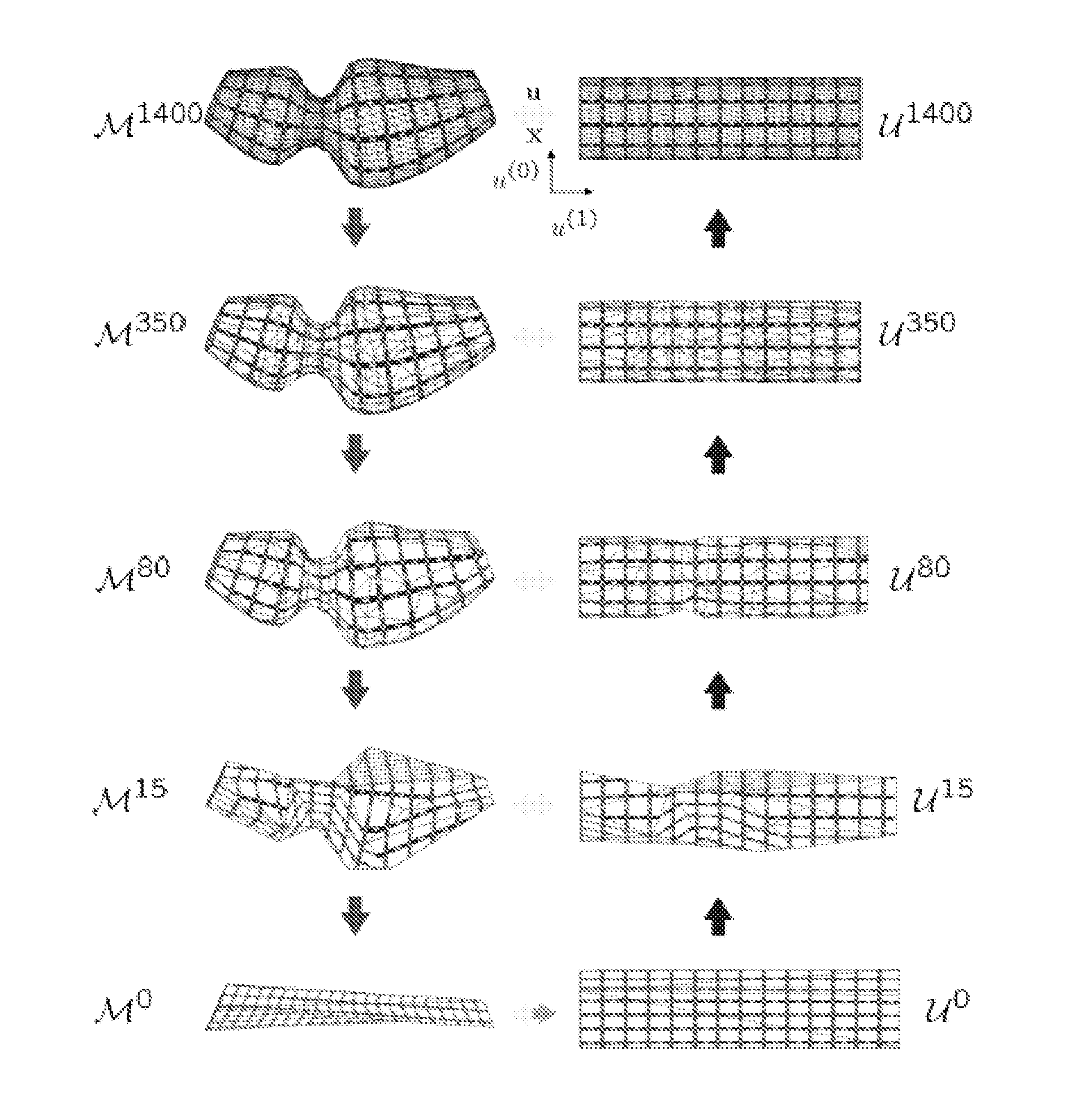
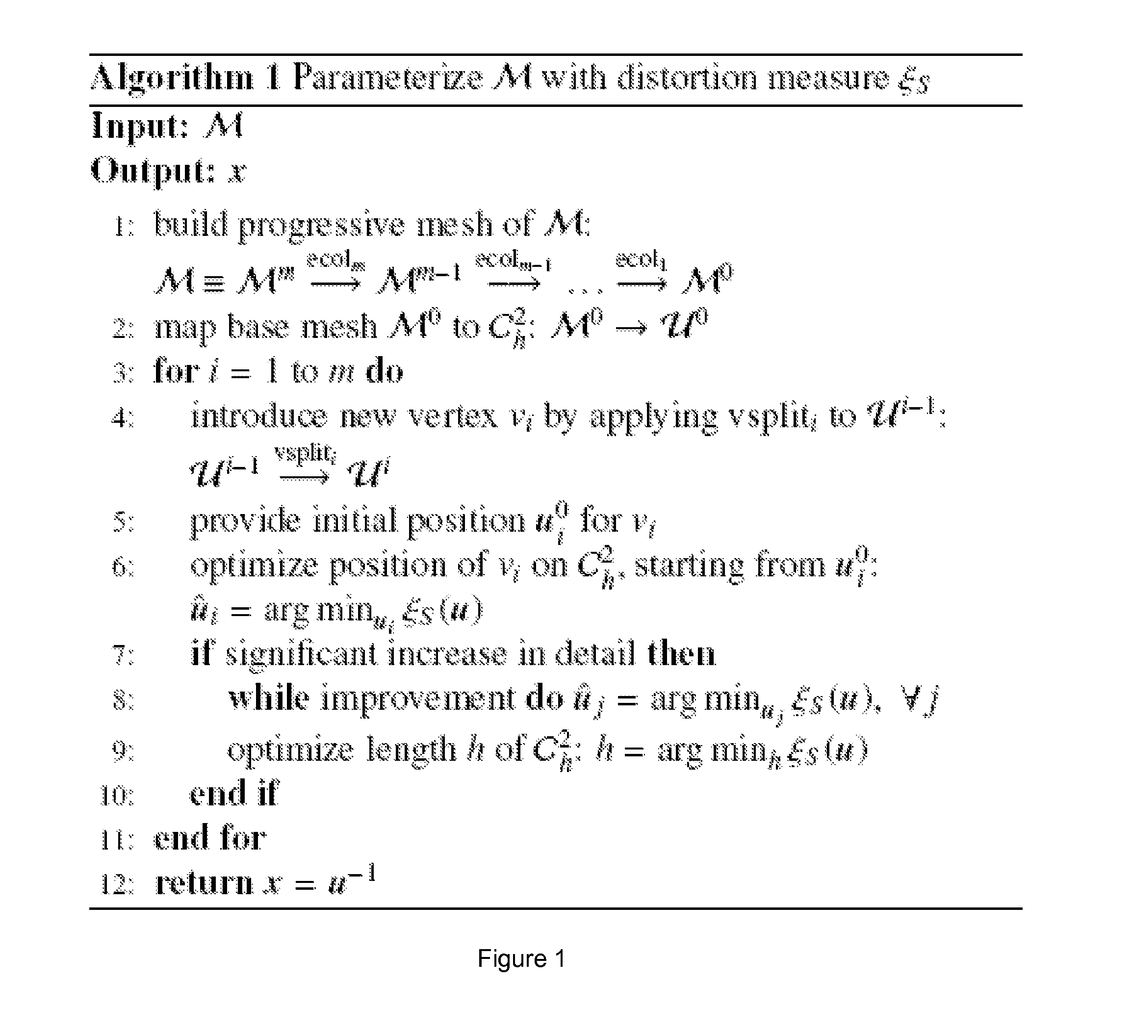
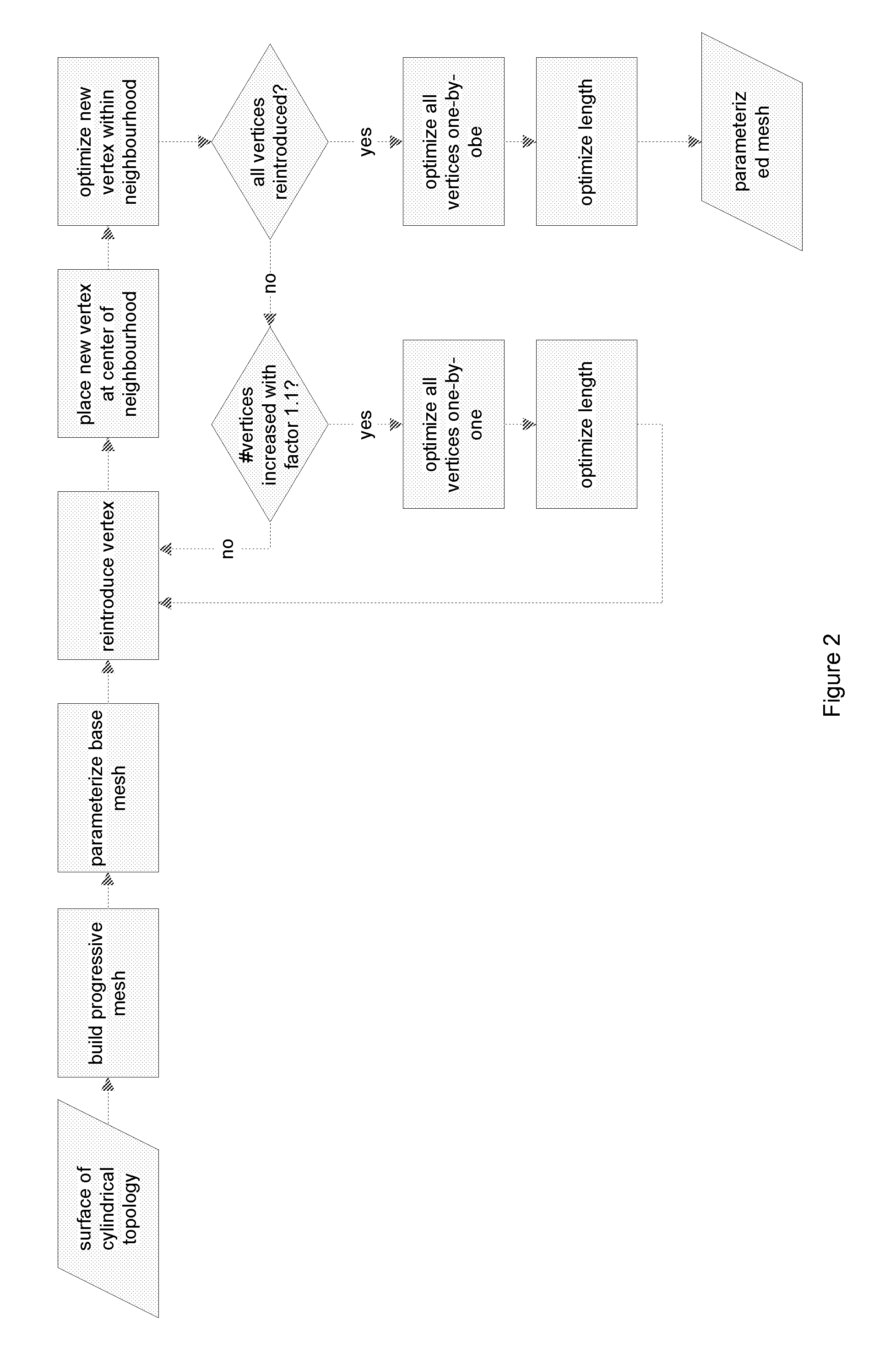
[0152]When using the method as described above, a dissection view of the colon is generated. The method starts from the surface of the colon wall that has the topology of an open ended cylinder. This surface is first progressively parameterized to an open-...

example 2

Comparison of Colon Stretch Method with Conformal Method

[0158]The topologically cylindrical colon surface M, counting 1.3M triangles, was extracted from a CT data set of the abdomen. The CT volume measured 512×512×532 voxels of size 0.78×0.78×0.8 mm3. The colon surface was parameterized using the progressive stretch minimization technique of this invention and also using the conformal method of Haker et al. (2000b). Both parameterizations were unfolded to the plane and rendered with the techniques of Section 2.2 and Section 2.3. The resulting unfolding is shown in FIG. 10. FIG. 10 illustrates: (a) Surface of the colon. (b) Magnification of part of the colon surface that exhibits significant down-sizing in the conformal flattening. (c) Flattened colon using conformal method. The final rendering is shown at the top and a map of the area distortion and the angle distortion is shown at the bottom. (d) same as in (c) but for the stretch optimization method. (e) Magnification of part of t...

example 3

Linear Parameterization for Cylindrical Surfaces

[0162]This example further illustrates the construction of the three sparse matrices A, C and E as mentioned above.

[0163]The Dirichlet energy, the Laplacian operator, and the boundary conditions will all be formulated in terms of the lengths of the edges uij of the embedding of K in C2h. The length of uij can be calculated using the coordinates of the end points ui and uj of the edge, i.e.

[0164]uij2=⁢ui⁢-uj2=⁢(ui(0)-uj(0))2+(ui(1)-uj(1))2.(4)

Since the parameterization domain is periodic along parameter u(0), some edges will cross the parametric seam u(0)=0=2π. For those edges, the above expression does not calculate the correct length. Given a surface M, a vertex path VP, connecting ∂M0 with ∂M1, is introduced on the surface. The path Vp should not self-intersect and it can have only one vertex on each boundary. The neighbouring vertices of the path VP are divided in two groups: VL are the neighbours on the left side and VR are the nei...


PUM


Abstract

Methods of cylindrical surface parameterization, such as colon flattening are provided for parameterizing tubular surfaces onto a cylinder, wherein the length of the cylinder is modified so that parameterization distortion is reduced.

Description

CROSS-REFERENCE TO RELATED APPLICATION[0001]This application is the U.S. national phase of PCT Appln. No. PCT / EP2010 / 057882 filed Jun. 7, 2010 which claims priority to European application EP 09162289.4 filed Jun. 9, 2009, the disclosures of which are incorporated in their entirety by reference herein.FIELD OF THE INVENTION[0002]The present invention relates to the field of surface parameterization. More specifically, the present invention relates to the field of cylindrical surfaces, such as a colon, where the methods of the invention can be used in virtual colonoscopy.BACKGROUND OF THE INVENTION[0003]Computed Tomography Colonography (CTC) or Virtual Colonoscopy (VC) is a minimally-invasive alternative to conventional optical colonoscopy to detect polyps of the colon wall. CTC has significantly evolved since then and is now emerging as a possible screening technique for colorectal cancer. The CTC technique combines computer tomography of the abdomen with specialized visualization t...

Claims


Application Information

Patent Timeline
Patent Type & Authority Patents(United States)
IPC IPC(8): G06T17/00G06T15/00G06T17/20
CPCG06T17/20G06T17/205
Inventor HUYSMANS, TOONSIJBERS, JAN
Owner UNIVERSITY OF ANTWERP
Why Eureka
Try Eureka