Positioning structure, positioning securing structure and electronic device

a technology of positioning securing structure and plate-shaped structure, which is applied in the direction of threaded fasteners, electrical apparatus casings/cabinets/drawers, instruments, etc., can solve the problems of inconvenient practical operation, time-consuming and complex, and the circuit layout of the motherboard may become complicated, so as to accurately position and secure the plate-shaped structure

Inactive Publication Date: 2015-01-20
LITE ON TECH CORP +1
View PDF8 Cites 8 Cited by
  • Summary
  • Abstract
  • Description
  • Claims
  • Application Information

AI Technical Summary

Benefits of technology

[0011]More precisely, when the outer surrounding surface of the positioning portion of the positioning element is inserted into the positioning hole to contact with the inner surface of the positioning hole, the positioning portion of the position element can be positioned in the positioning hole, thus the positioning structure, the positioning securing structure and the electronic device can be used to accurately position and secure the plate-shaped structure.

Problems solved by technology

In the conventional manner of screwing and fixing the motherboard through using the stand off, during the process of assembling and disassembling the motherboard, the user must repeatedly screw and unscrew the bolts one by one, so it is quite time consuming and complex, which is quite inconvenient in the practical operations.
The current electronic devices are required to be light, thin, short, and small, too many stand off may occupy too much area on the motherboard, as a result, the circuit layout on the motherboard may become complicated, and the overall electronic device cannot be miniaturized.
More importantly, the motherboard still cannot be accurately positioned on a predetermined position due to the offset of the motherboard by using the stand off.

Method used


Image

  • Positioning structure, positioning securing structure and electronic device
  • Positioning structure, positioning securing structure and electronic device
  • Positioning structure, positioning securing structure and electronic device

Examples


Embodiment Construction

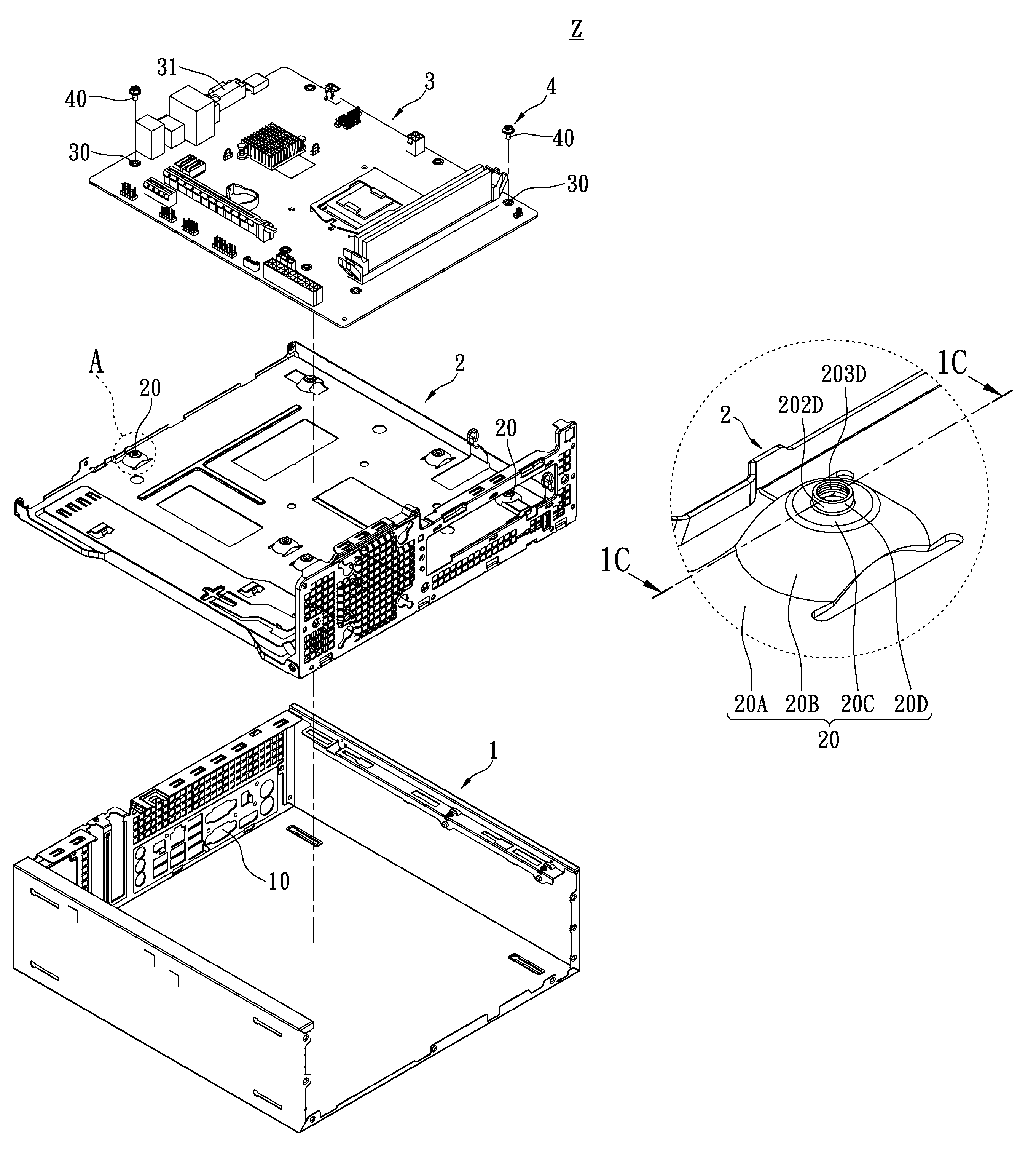
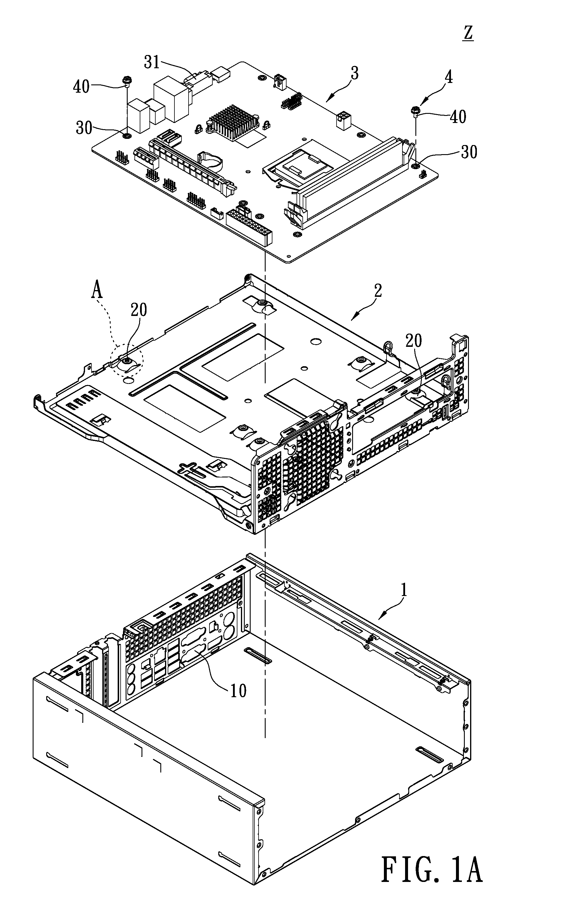
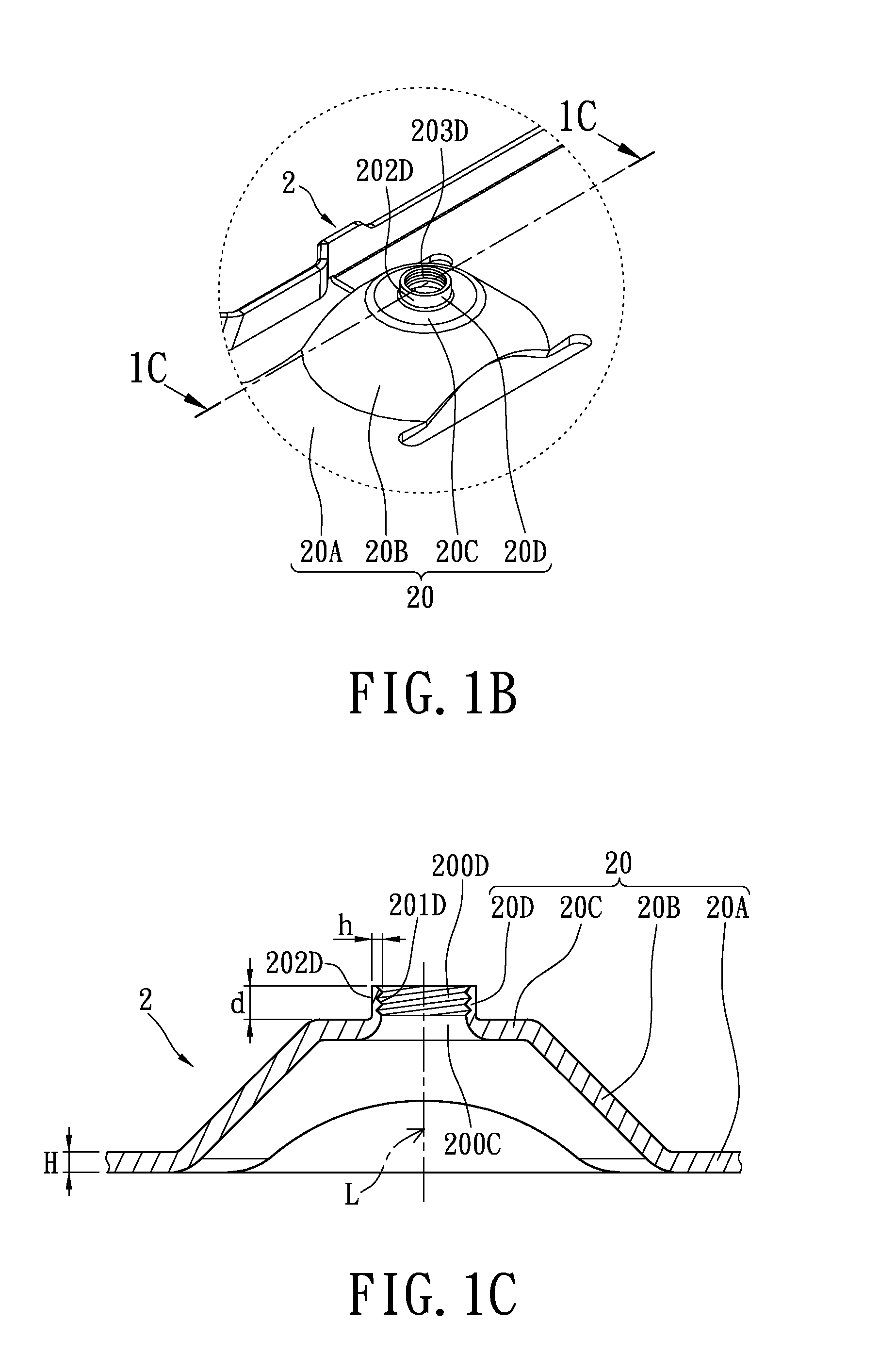
[0022]Referring to FIG. 1A to FIG. 3C, where FIG. 1A is a perspective, exploded, schematic diagram, FIG. 2A is a partial, perspective, exploded, schematic diagram, FIG. 3A is a perspective, assembled, schematic diagram, FIGS. 1B, 2B and 3B are enlarged diagrams, and FIGS. 1C, 2C and 3C are cross-sectional diagrams. The instant disclosure provides an electronic device Z comprises a casing structure 1, a positioning structure 2, a plate-shaped structure 3 and a securing structure 4, where the plate-shaped structure 3 includes a plurality of electrical connectors 31.

[0023]First, referring to FIG. 1A, the casing structure 1 may be a computer chassis for a computer host, thus the casing structure 1 may have a plurality of connector openings 10 formed in advance for respectively exposing the electrical connectors 31 of the plate-shaped structure 3. However, the casing structure 1 used in this embodiment is merely an example and is not meant to limit the instant disclosure.

[0024]Moreover, ...


PUM


Abstract

A positioning structure for positioning a plate-shaped structure having at least one positioning hole is disclosed. The positioning structure includes at least one positioning element corresponding to the positioning hole, and the positioning element includes a placement portion for supporting the plate-shaped structure and a positioning portion extending toward a direction far away from the placement portion to form a hollow cylinder shape, and the positioning portion has an outer surrounding surface and a plurality of inner threads. Hence, when the outer surrounding surface of the positioning portion of the positioning element is inserted into the positioning hole to contact with the inner surface of the positioning hole, the positioning portion of the position element can be positioned in the positioning hole, thus the instant disclosure can be used to accurately position and secure the plate-shaped structure.

Description

BACKGROUND OF THE INVENTION[0001]1. Field of the Invention[0002]The instant disclosure relates to a positioning structure, a positioning securing structure and an electronic device, and more particularly, to a positioning structure for positioning a plate-shaped structure, a positioning securing structure for positioning and securing a plate-shaped structure, and an electronic device using a positioning securing structure.[0003]2. Description of Related Art[0004]Recently, as the vigorous development of science and technology and information, computer equipment has become a quite popularized electronic device. As for the computer equipments available on the current market, no matter desktop computers, notebooks or servers, a motherboard must be installed therein to serve as a core member for the computer system, such that the central processing unit (CPU), memory module, peripheral controller interface (PCI) card, and other computer peripheral hardware electrically connected onto the...

Claims


Application Information

Patent Timeline
Patent Type & Authority Patents(United States)
IPC IPC(8): H05K7/04H05K7/02
CPCG06F1/184Y10T403/3986F16B5/02F16B37/0807
Inventor TU, CHUN TANGTSENG, CHUAN-CHIEHLIU, YUNG-LUNG
Owner LITE ON TECH CORP
Why Eureka
Try Eureka