

Workpiece welding positioning work fixture
A technology of welding positioning tooling and fixtures, which is applied in the direction of manufacturing tools, welding equipment, auxiliary welding equipment, etc., can solve the problems of unstable welding quality of welding workpieces, and achieve the effects of improving workpiece assembly efficiency, improving stability, and prolonging service life
- Summary
- Abstract
- Description
- Claims
- Application Information
AI Technical Summary
Problems solved by technology
Method used
Image

Examples
Embodiment 1
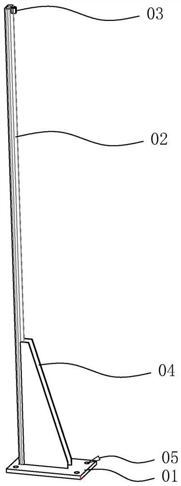
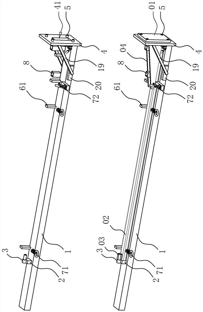
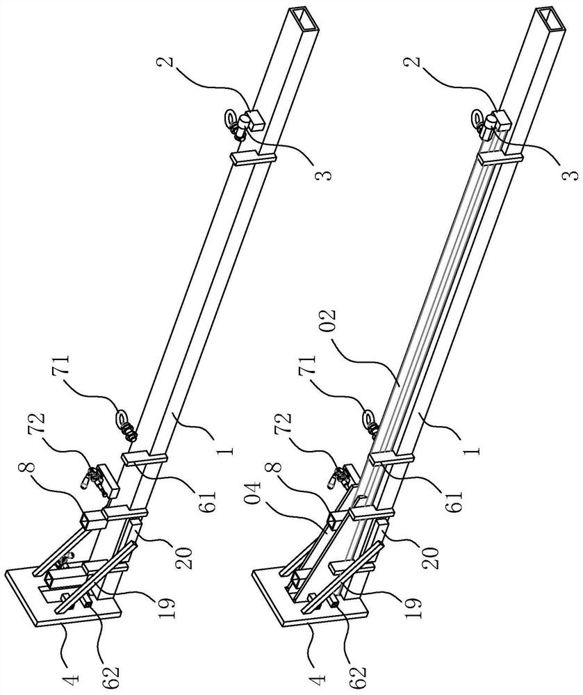
[0040] The present invention is a welding positioning fixture, such as 2 and image 3, as shown, includes a tooling table 1 made of hollow square steel profiles, and a rod positioning piece 2 made of a hollow steel pipe is welded and fixed on the upper surface of one end of the tooling table 1; , the positioning pin 3 includes a mounting column plugged with the connecting nut 03 and a connecting cylinder abutting against the connecting nut 03, the connecting cylinder and the mounting column are coaxially arranged and the diameter of the connecting column is greater than the diameter of the mounting column; the tooling table 1 is far away from One end of the rod positioning member 2 is welded to a rectangular positioning plate 4, and a rectangular avoidance groove 41 is provided in the middle of the positioning plate 4, which is used to penetrate the wall of the reinforcing plate 04 to facilitate spot welding connection between the reinforcing plate 04 and the bottom plate 01. T...
Embodiment 2
[0044] The embodiment of the present application discloses a workpiece welding positioning fixture, referring to Figure 4 with Figure 5 , the positioning column 8 is welded and fixed on the same turning plate 9, the end of the turning plate 9 near the positioning plate 4 is welded and fixed with a cylindrical active shaft 10, the axis of the active rotating shaft 10 is parallel to the plate surface of the positioning plate 4, and the positioning plate 4 The end away from the tooling table 1 is fixed with a rotating sleeve 11, and the active rotating shaft 10 is rotated and inserted in the rotating sleeve 11; the side of the active rotating shaft 10 away from the tooling table 1 is provided with a limit plate 18 welded and fixed on the positioning plate 4 , the limiting plate 18 is parallel to the positioning plate 4, and the limiting plate 18 limits the rotation angle of the turning plate 9.
[0045] A driven shaft 13 is rotatably inserted in the tooling table 1, and the dr...
PUM
 Abstract
Description
Claims
Application Information