
Imaging lens

a technology of imaging lens and lens body, applied in the field of imaging lenses, can solve the problems of structurally impossible application of imaging lens, difficulty in achieving the effect of adjusting the f-value, wide angle of view, and small f-valu

Active Publication Date: 2015-01-27
TOKYO VISIONARY OPTICS CO LTD
View PDF5 Cites 2 Cited by
  • Summary
  • Abstract
  • Description
  • Claims
  • Application Information

AI Technical Summary

Benefits of technology

[0006]The present invention has been made in view of the problem of the conventional techniques and has an objective to provide an imaging lens which features compactness, a relatively wide angle of view and a small F-value and corrects aberrations properly. In particular, the invention provides a thin imaging lens which copes with the trend toward smaller sensor sizes.

Problems solved by technology

If the above refractive power and lens surface combination is used to achieve further compactness, it would be difficult for each constituent lens to have an adequate center thickness and an adequate edge thickness.
When the constituent lenses are manufactured by injection molding, this would pose a problem that resin filling work may be difficult.
It is structurally impossible to apply this imaging lens, for example, to a small image sensor of ⅕ inch or less while keeping the ratio of total track length to maximum image height low.
In addition, the half angle of view is about 33 degrees, so the angle of view is not sufficiently wide.

Method used


Image

  • Imaging lens
  • Imaging lens
  • Imaging lens

Examples


first embodiment

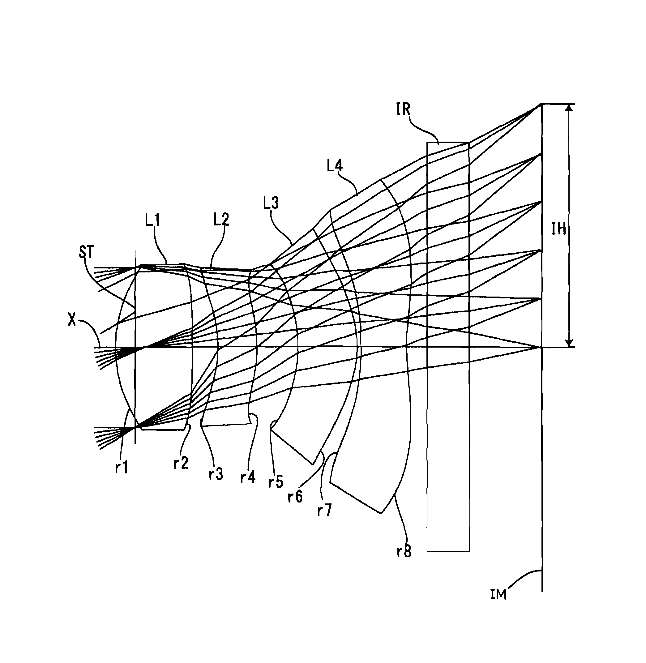
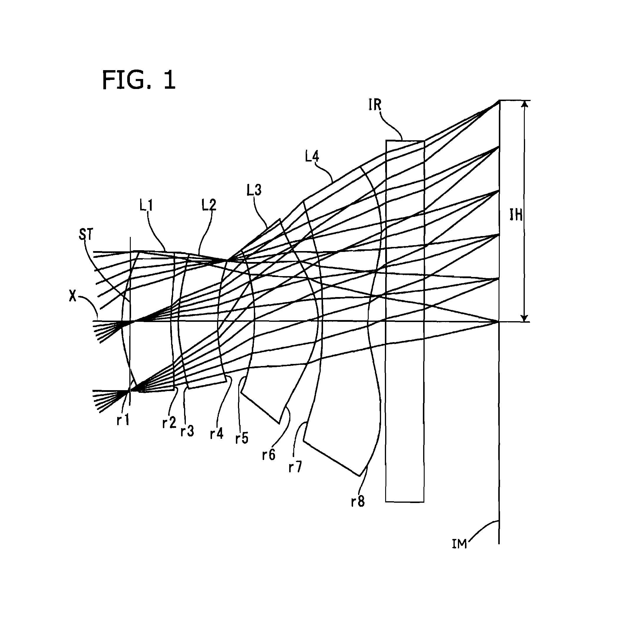
[0067]A first embodiment of the present invention will be described in detail referring to drawings. FIGS. 1, 3, 5, 7, 9, 11, 13, and 15 are sectional views of the imaging lenses as Examples 1 to 8 according to the first embodiment respectively.

[0068]In all the examples according to the first embodiment, an aperture stop ST is located in the effective diameter peripheral area of the object-side surface r1 of the first lens L1. A filter IR which includes surfaces r9 and r10 is located between the image-side surface r8 of the fourth lens L4 and the image plane IM. In the figures, X represents an optical axis. In calculation of a distance on the optical axis, the filter IR (r9 and r10) is removed.

[0069]In the first embodiment, all the lens surfaces are aspheric. The aspheric shape of each of these lens surfaces is expressed by Equation 1, where Z represents the optical axis direction, H represents height in a direction perpendicular to the optical axis, k represents conic constant, and...

example 1

[0072]As shown in FIG. 1, in the imaging lens as Example 1, the first lens L1 is a meniscus lens with positive refractive power having a convex surface on the object side near the optical axis X, the second lens L2 is a meniscus lens with positive refractive power having a convex surface on the object side near the optical axis X, the third lens L3 is a meniscus lens with positive refractive power having a convex surface on the image side near the optical axis X, and the fourth lens L4 is a lens with negative refractive power having a biconcave shape near the optical axis X. The image-side aspheric surface r8 of the fourth lens L4 has a pole-change point in a position off the optical axis X. All the lenses are made of the same plastic material.

[0073]The basic lens data of Example 1 is shown in Table 1.

[0074]

TABLE 1Embodiment 1Unit mmf =1.710Fno =2.20ω(°) =39.75IH =1.234Surface DataCurvatureSurfaceRefractiveAbbe NumberSurface No. iRadius rDistance dIndex Ndvd(Object Surface)InfinityI...

example 2

[0079]As shown in FIG. 3, in the imaging lens as Example 2, the first lens L1 is a lens with positive refractive power having a biconvex shape near the optical axis X, the second lens L2 is a meniscus lens with positive refractive power having a convex surface on the image side near the optical axis X, the third lens L3 is a meniscus lens with positive refractive power having a convex surface on the image side near the optical axis X, and the fourth lens L4 is a lens with negative refractive power having a biconcave shape near the optical axis X. The image-side aspheric surface r8 of the fourth lens L4 has a pole-change point in a position off the optical axis X. All the lenses are made of the same plastic material.

[0080]The basic lens data of Example 2 is shown in Table 2.

[0081]

TABLE 2Embodiment 2Unit mmf =1.970Fno =2.45ω(°) =35.64IH =1.234Surface DataCurvatureSurfaceRefractiveAbbe NumberSurface No. iRadius rDistance dIndex Ndvd(Object Surface)InfinityInfinity(Stop)Infinity−0.100 1...


PUM


Abstract

An imaging lens includes four lenses arranged in order from the object side to the image side: an aperture stop, positive (refractive power) first lens having a convex object-side surface near the optical axis, second lens having a positive meniscus shape near the axis, positive third lens having a convex image-side surface near the axis, and negative fourth lens having a concave image-side surface near the axis. All lens surfaces are aspheric. The image-side aspheric surface of the fourth lens has a pole-change point off the optical axis and conditional expressions (1) and (2) are satisfied:0.75<TLA / (2IH)<0.90  (1)0.90<TLA / f<1.30  (2)whereTLA: distance on the optical axis from the first lens's object-side surface to the image sensor's image plane without a filter between the fourth lens and image sensorIH: maximum image heightf: overall optical system focal length.

Description

[0001]The present application is based on and claims priority of Japanese patent applications No. 2012-169974 filed on Jul. 31, 2012, and No. 2013-122383 filed on Jun. 11, 2013, the entire contents of which are hereby incorporated by reference.BACKGROUND OF THE INVENTION[0002]1. Field of the Invention[0003]The present invention relates to imaging lenses which form an image of an object on a CCD sensor or C-MOS sensor used in a compact image pickup device and more particularly to image pickup devices with an imaging lens which are mounted in mobile terminals such as mobile phones and smart phones which are becoming increasingly compact and thin, and PDAs.[0004]2. Description of the Related Art[0005]In recent years, personal digital assistants (PDAs) and smart phones as mobile phones with a computer function have become more popular than mobile phones mainly designed for calls. The imaging lenses which are mounted in these mobile terminals and smart phones are expected to be small and...

Claims


Application Information

Patent Timeline
Patent Type & Authority Patents(United States)
IPC IPC(8): H04N5/222G02B13/16H04N9/07H04N5/228H04N5/225G02B13/00G02B15/14
CPCG02B15/14G02B13/004G02B9/34
Inventor SEKINE, YUKIOSUZUKI, HISANORI
Owner TOKYO VISIONARY OPTICS CO LTD
Learn More