Firearm suppressor and injector assembly

a technology of injector and suppressor, which is applied in the direction of weapons, mechanical equipment, machines/engines, etc., can solve the problems of reducing the muzzle sound level, affecting the life of well under 100 shots, and affecting the effect of the muzzle sound

Inactive Publication Date: 2015-02-10
STORRS INVESTMENTS L L C
View PDF5 Cites 29 Cited by
  • Summary
  • Abstract
  • Description
  • Claims
  • Application Information

AI Technical Summary

Benefits of technology

[0009]In accordance with one aspect of the invention, a suppressor assembly for connection to the muzzle of a firearm includes an injector portion adapted for connection to the muzzle, the injector portion having a chamber for holding a quantity of fluid; and a suppressor portion connectable to the injector portion, the suppressor portion being in fluid communication with the injector portion. With this arrangement, fluid is drawn from the chamber and into the suppressor portion when a fired projectile passes therethrough to thereby shield the suppressor portion from full impact of gases associated with the fired projectile.
[0010]In accordance with a further aspect of the invention, an injector assembly for connection to the muzzle of a firearm includes an outer injector cover; a core portion; a distal end wall located at one end of the core portion; a proximal end wall located at an opposite end of the core portion; a central bore extending through the core portion, the central bore being sized for receiving a projectile upon discharge of the firearm; the chamber being formed between the outer cover, the core portion, and the distal and proximal end walls for receiving a quantity of fluid; and at least one aperture extending between the chamber and the central bore for fluidly connecting the central bore and the chamber. In this manner, the discharged projectile passing through the central bore of the core portion and across the at least one aperture creates a vacuum in the chamber to thereby draw fluid from the chamber and into the central bore to thereby lubricate and cool the injector assembly.

Problems solved by technology

Although such arrangements are more complex, they can provide more capacity to delay and cool the gases, and hence reduce the muzzle sound level.
However, such structures wear out quickly, resulting in a service life of well under 100 shots.
No matter what the type of baffle is used in the suppressor, it often becomes difficult to remove from the suppressor housing for cleaning, as tough residue from the discharge gases can build up quickly in and around crevices, creating a bond between the suppressor components which can be difficult to break.
Moreover, baffles closer to the muzzle end of the firearm are subjected to greater pressure, contaminants, heat from the firearm flash during discharge, etc., than baffles located further away from the muzzle end, thereby causing premature wear and failure of the suppressor.

Method used


Image

  • Firearm suppressor and injector assembly
  • Firearm suppressor and injector assembly
  • Firearm suppressor and injector assembly

Examples


Embodiment Construction

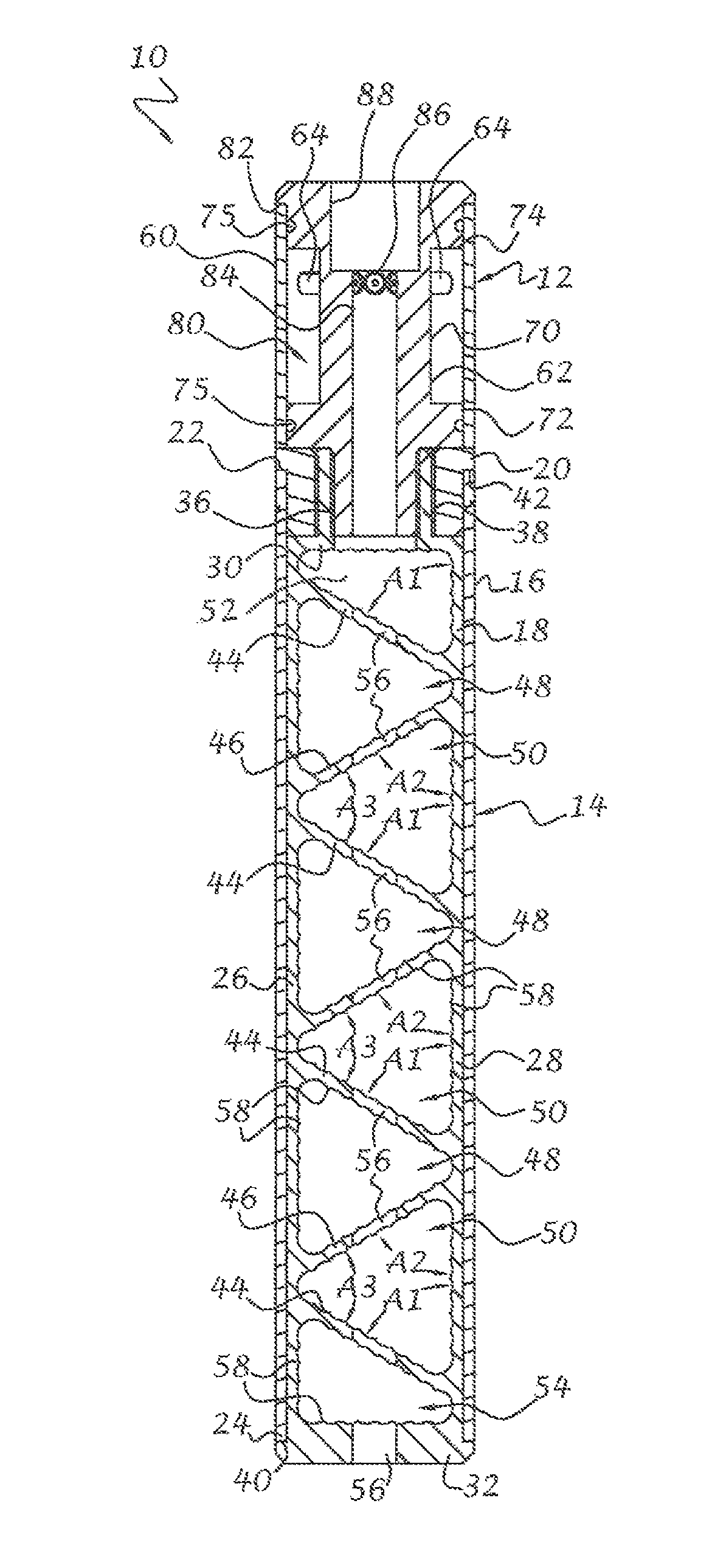
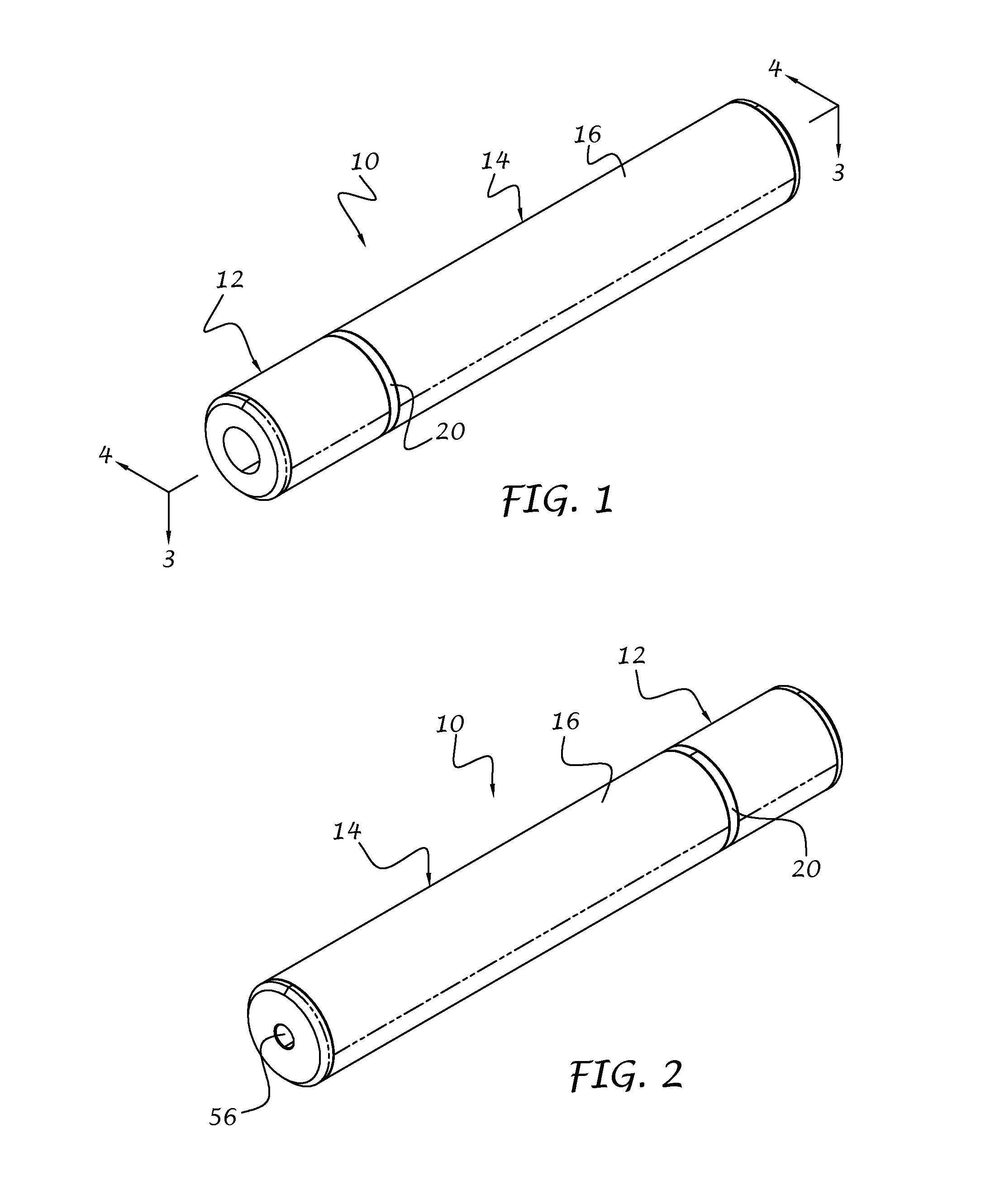
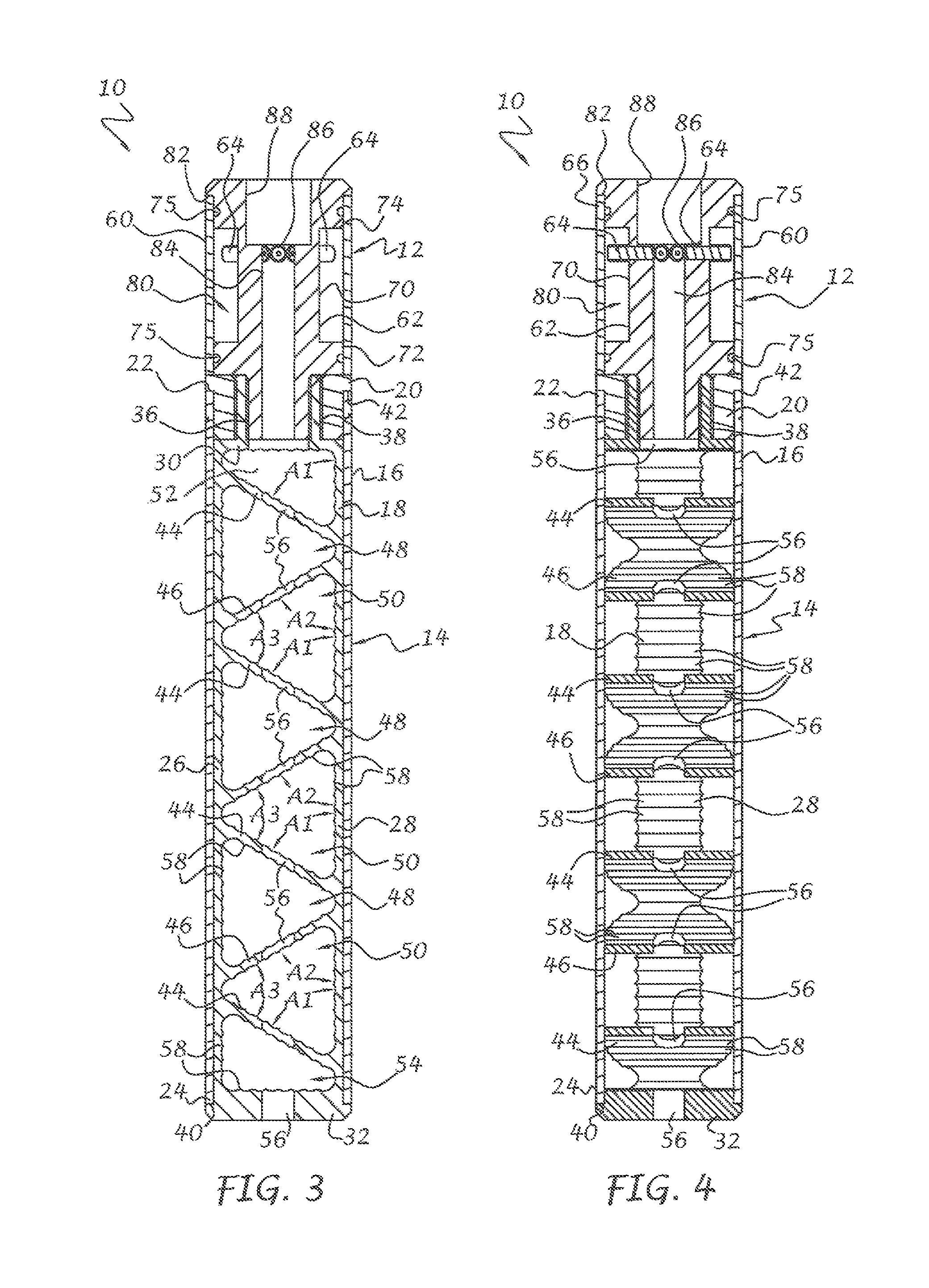
[0020]Referring to the drawings, and to FIGS. 1 and 2 in particular, a firearm suppressor assembly 10 in accordance with one embodiment of the present invention is illustrated. The suppressor assembly 10 is adapted for coupling to the muzzle of a firearm (not shown). The suppressor assembly 10 can be adapted for practically any type of firearm, including but not limited to, large and small caliber rifles, handguns, single-shot, semi-automatic and fully automatic guns, bolt-action rifles, shotguns, rim-fire and center-fire guns, and so on. The suppressor assembly 10 preferably includes an injector portion 12 connected to a suppressor portion 14. The injector portion 12 serves to enhance the muffling effect of the suppressor portion 14 and can also serve as a flash suppressor, muzzle break, or other adapter, although a separate flash suppressor, etc. (not shown) can also be used. In addition, although the injector portion 12 and suppressor portion 14 are shown as separate units, it wi...


PUM


Abstract

A suppressor assembly for connection to the muzzle of a firearm includes an injector portion for connection to the muzzle and a suppressor portion for connection to the injector portion. The injector portion has a chamber for holding a quantity of fluid. When a firearm is discharged and the projectile passes through the injector portion, fluid is drawn from the chamber and into the suppressor portion to thereby shield the suppressor portion from full impact of gases associated with the fired projectile. The injector and suppressor portions can be operated independently and the injector portion can also function as a muzzle break, flash suppressor, and so on.

Description

CROSS-REFERENCE TO RELATED APPLICATIONS[0001]This application claims the benefit of U.S. Provisional Application No. 61 / 650,383 filed on May 22, 2013, the disclosure of which is hereby incorporated by reference.FIELD OF THE INVENTION[0002]This invention relates to firearm accessories, and more particularly to a sound suppressor or silencer, as well as an injector assembly connectable between the suppressor and firearm.BACKGROUND OF THE INVENTION[0003]Suppressors for firearms, also known as silencers, generally operate to reduce the audible noise or sharp report of a firing weapon by means of reducing and controlling the energy level of attendant propellant gases. Generally, the techniques include the provision of a series of baffles which control and delay the flow, expansion, and discharge of propellant gases, forcing the propellant gases to pass through various temperature absorbent materials, or a combination of these or functionally similar techniques to reduce the temperature a...

Claims


Application Information

Patent Timeline
Patent Type & Authority Patents(United States)
IPC IPC(8): F41A21/30F01N3/02
CPCF01N3/02F41A21/30
Inventor STORRS, NORVENTODD, JAROD
Owner STORRS INVESTMENTS L L C
Why Eureka
Try Eureka