
Starter motor

a starter motor and motor technology, applied in the direction of electric generator control, electric motor propulsion transmission, locomotive transmission, etc., can solve the problems of occupying space, vulnerable to external damage, and complex structure of starter motor, and achieve the effect of simple structur

Inactive Publication Date: 2015-02-10
JOHNSON ELECTRIC SA
View PDF22 Cites 0 Cited by
  • Summary
  • Abstract
  • Description
  • Claims
  • Application Information

AI Technical Summary

Benefits of technology

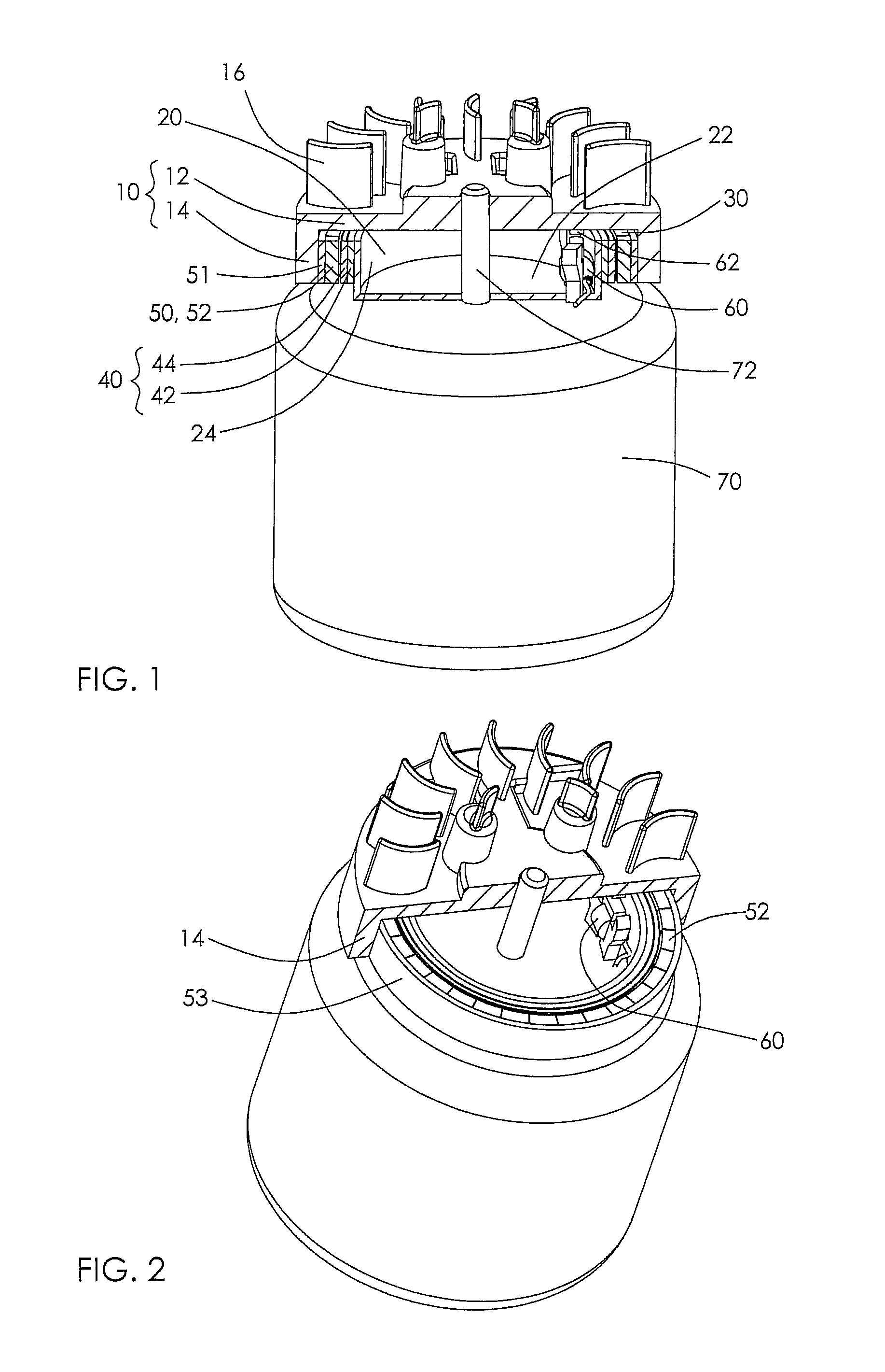
The patent text describes a device called a drive device that uses a special type of motor to generate power. The device has a rotor that is fixed to the inside of a flywheel, which is designed to rotate. The rotor has a part called a squirrel cage, which supports an electrical conductor. The stator, which is the part of the motor that produces electricity, faces the conductor on the rotor. This design allows for efficient and reliable power production.

Problems solved by technology

However, the above starter motor comprises a motor, gearbox and pinion installed outside of the flywheel where it is vulnerable to external damage.
The starter motor has a complicated structure and occupies space.

Method used


Image

  • Starter motor
  • Starter motor
  • Starter motor

Examples


third embodiment

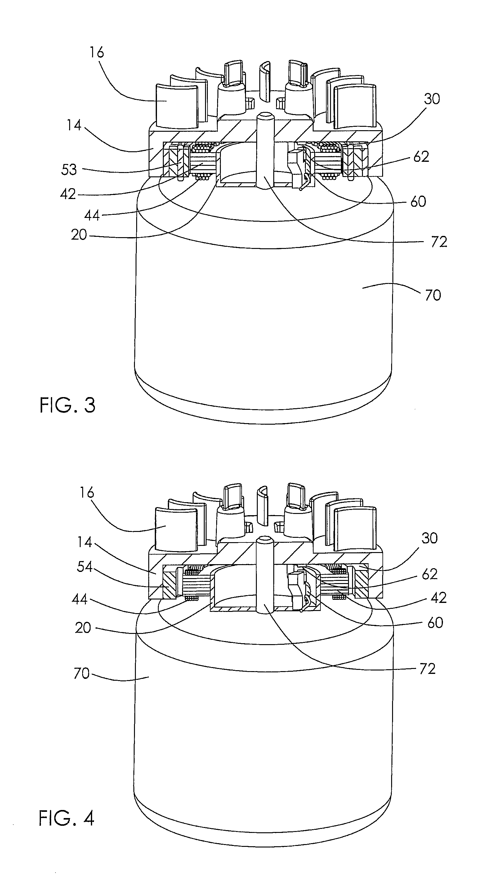
[0035]FIGS. 4 and 5 show a starter motor of the present invention. This starter motor adopts a SR (switched reluctance) motor structure. The rotor comprises a rotor core 54 fixed on the inner surface of the side wall 14 of the flywheel 10. The rotor core 54 comprises a plurality of teeth 55 extending inwardly there from. The teeth 55 face the stator winding 44. The rotor of this embodiment does not use a permanent magnet and no core loss is generated when the engine rotates and the current of the stator winding 44 is cut off.

fourth embodiment

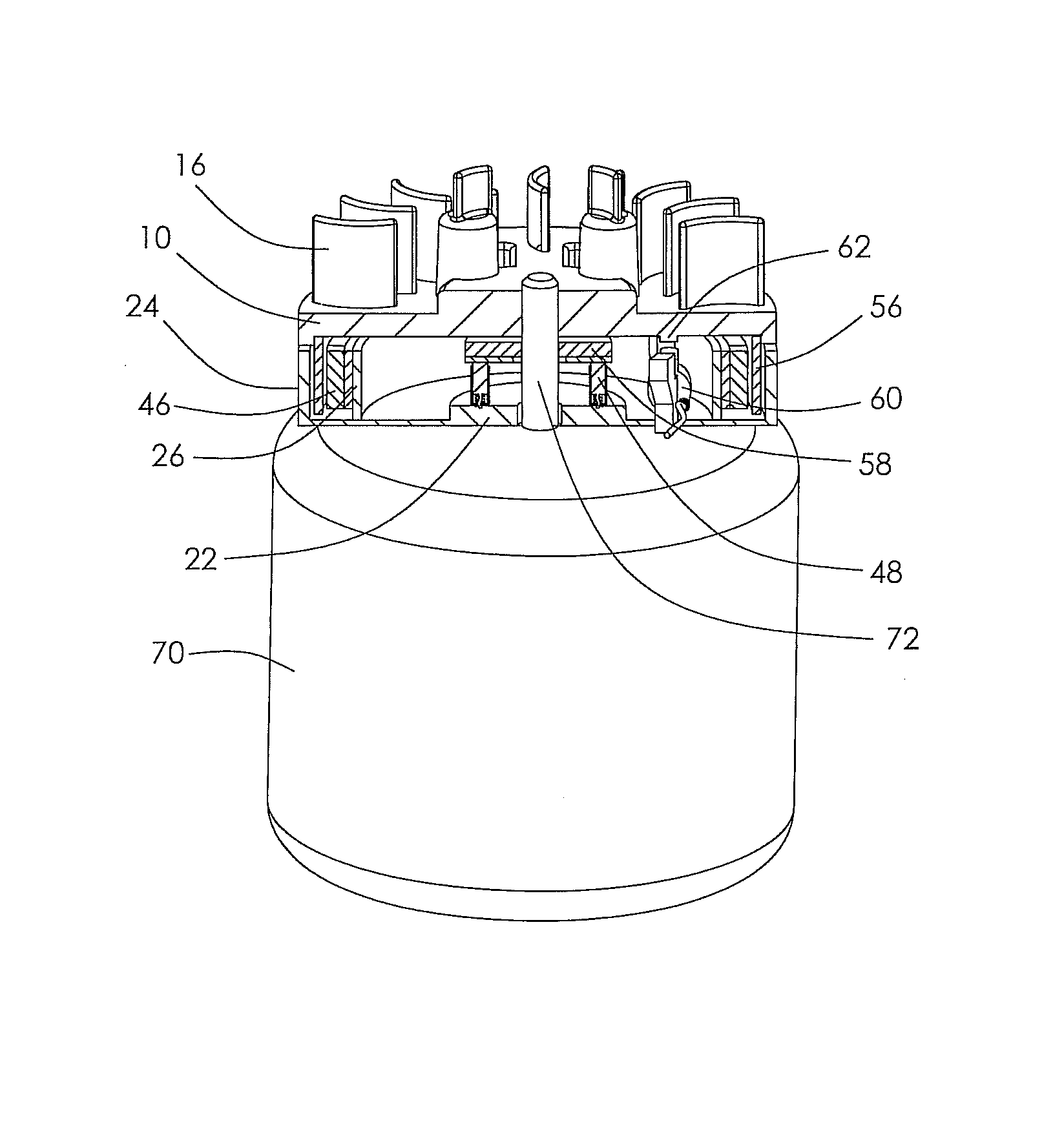
[0036]FIGS. 6 and 7 show a starter motor of the present invention. This starter motor adopts a coreless direct current motor structure. The support 20 comprises a side wall 24 and an inner wall 26. The stator 40 comprises a magnet 46 fixed on the outer surface of the inner wall 26. The rotor comprises rotor windings 56 fixed on the inner surface of the side wall 14 of the flywheel 10. The windings 56 are located between the magnet 46 and side wall 24 of the support 20 with a small air gap formed there between. The motor further comprises a commutator 58 fixed to the shaft 72 of the engine 70, or the inner surface of the end wall 12 of the flywheel, and electrically connected to the rotor windings 56. Brushes 48 are installed on the end wall of the support 20 for slidably contacting with the commutator 58 to thereby feed power from a power source to the rotor windings 56. A diode may be arranged between the power source and the starter motor to prevent current generated in the rotor ...


PUM


Abstract

A starter motor for engine has a flywheel fixed to a shaft of the engine. A support is fixed relative to the engine. A space is formed between the flywheel and the support and a driving device is installed in the space. The driving device includes a stator fixed to the support and a rotor fixed to the flywheel.

Description

CROSS REFERENCE TO RELATED APPLICATIONS[0001]This non-provisional patent application claims priority under 35 U.S.C. §119(a) from Patent Application No. 201010515070.2 filed in The People's Republic of China on Oct. 20, 2010.FIELD OF THE INVENTION[0002]This invention relates to a starter motor for an internal combustion engine and in particular, to a starter motor for an engine of a lawn mower or the like.BACKGROUND OF THE INVENTION[0003]FIG. 8 shows a traditional starter motor for an engine of a lawn mower. The starter motor comprises an electric motor 1, a reduction gearbox 2 connected to a shaft of the motor 1, an output shaft 3 of the gearbox 2, and a pinion 4 mounted on the output shaft 3. When the motor 1 is operated, the output shaft 3 is rotated to thereby drive the pinion 4. The pinion illustrated is an inertia type pinion which relies on the inertia of the pinion and a helical spline connection between the output shaft and the pinion to move the pinion axially along the ou...

Claims


Application Information

Patent Timeline
Patent Type & Authority Patents(United States)
IPC IPC(8): F02N11/00F02N15/00H02K7/14
CPCF02N11/00F02N15/006H02K7/14F02D2400/06
Inventor ZHANG, GUO JIGAN, JIN YUNLIU, LI SHENGLI, YUE
Owner JOHNSON ELECTRIC SA
Learn More