Head-up display device

a display device and head-up technology, applied in static indicating devices, instruments, transportation and packaging, etc., can solve the problem that the driver cannot sufficiently visually recognize the superimposed display information, and achieve the effect of preventing the up-sizing, convenient adjustment, and low cos

Active Publication Date: 2015-02-10
YAZAKI CORP
View PDF25 Cites 5 Cited by
  • Summary
  • Abstract
  • Description
  • Claims
  • Application Information

AI Technical Summary

Benefits of technology

[0020]According to the first aspect of the present invention, the position of the virtual images of the guide light by the luminous bodies travels in the vertical direction together with the position of the virtual image of the display information. Also, the amount of travel of the virtual images of the guide light when the reflector is displaced is smaller than the amount of travel of the virtual image of the display information. Therefore, even if the virtual image of the display information falls outside the projection area, the virtual images of the guide light remain in the projection area, and is displayed. For that reason, it can be easily determined whether the virtual image of the display information is located above or below the projection area, according to the position at which the virtual images of the guide light are displayed or the direction of the guide light, and the position of the display information can be vertically adjusted with precision. Also, the virtual images of the guide light are displayed (visually recognized) closer to the driver than the virtual image of the display information. Therefore, the virtual images of the guide light and the virtual image of the display information are visually recognized at the same time, thereby enabling the sense of distance to be achieved. Also, since the luminous bodies are disposed within the case, the device can be prevented from being upsized. Also, the device can be configured inexpensively without requiring a complicated mechanism.
[0021]According to the second aspect of the present invention, when the virtual image of the display information is displayed on the projection area so as to face the front of the driver, the virtual images of the guide light become horizontal. That is, when the virtual image of the display information is correctly displayed, the virtual images of the guide light become horizontal. For that reason, it can be determined whether the virtual image of the display information is located at a correct position, or not, according to whether the virtual images of the guide light are horizontal, or not, and the position of the virtual image of the display information can be easily adjusted.
[0022]According to the third aspect of the present invention, the virtual display of the guide light can travel along the visual recognition direction of the driver, that is, along a direction from the near side of the driver toward the back side, or a direction opposite thereto (front-back direction of vehicle). Therefore, the driver's attention can be drawn to the display of the HUD device, and a depth sense can be created in the visual recognition direction of the driver.
[0023]According to the fourth aspect of the present invention, since the virtual images of the guide light are largely displayed, the visibility of the guide light can be improved. Also, the display light of the display information reflected from the inner surface of the case toward the reflector is shielded by the light guide member. Also, the display light of the display information is prevented from being reflected by the light emitting surface. As a result, a ghost (dual display) of the virtual image of the display information, and the deterioration of a contrast of the virtual image by lightening the interior of the case are prevented, thereby enabling the visibility of the display information to be improved.

Problems solved by technology

For that reason, in the HUD device where a range (hereinafter referred to as “eye range”) of an eye position at which the virtual image of the display information displayed on the projection area can be viewed is limited, unless the display light forming the virtual image of the display information faces the driver's eyes, the driver cannot sufficiently visually recognize the superimposed display information.

Method used


Image

  • Head-up display device
  • Head-up display device
  • Head-up display device

Examples


first embodiment

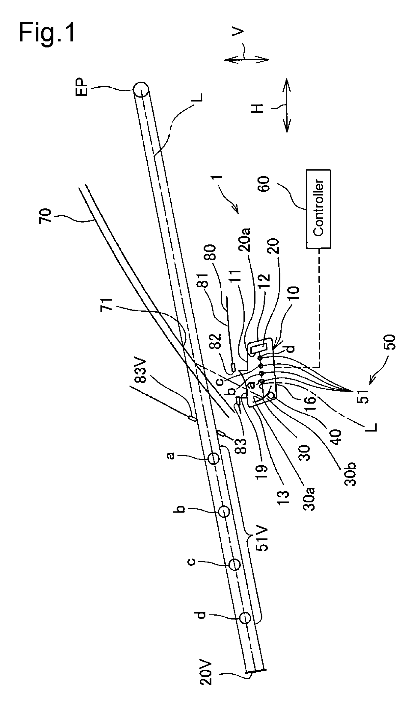
[0048]Hereinafter, a head-up display device according to a first embodiment of the present invention will be described with reference to FIGS. 1 to 15(c).

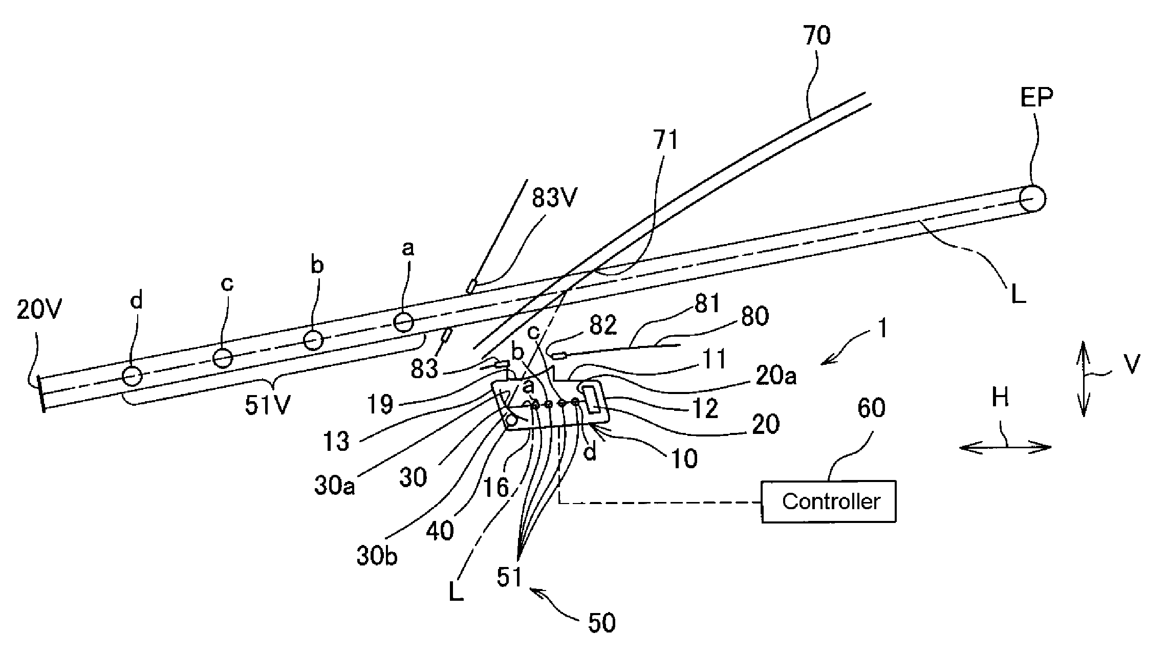
[0049]As illustrated in FIG. 1, a head-up display (HUD) device 1 includes a case 10, a display source 20, a reflector 30, a driver 40 as a reflector displacement unit, a guide light unit 50, a controller 60, and an operating unit not shown. The HUD device 1 is equipped within a dashboard 80 facing a window shield (window shield glass) 70 of the vehicle.

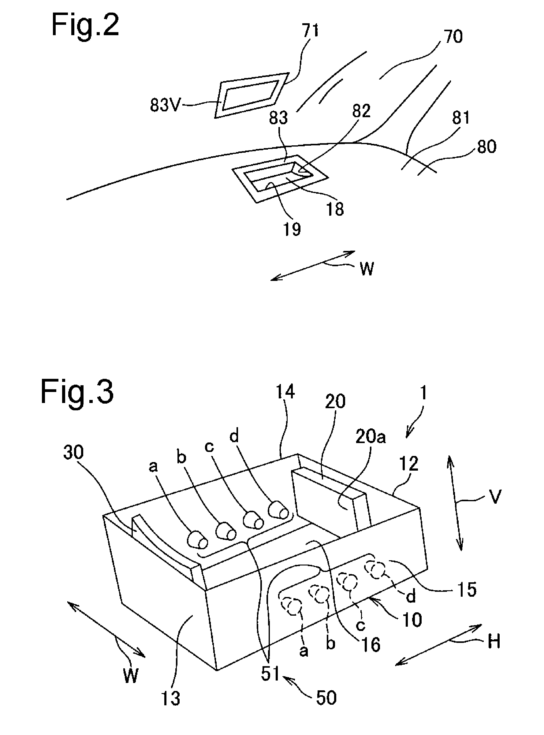
[0050]The window shield 70 is provided with a rectangular projection area 71. To the projection area 71 are projected a light emitted by an opening bezel 83 that will be described later, a display light L of the display source 20, which will be described later, provided in the HUD device 1, and a guide light of the guide light unit 50.

[0051]As illustrated in FIGS. 1 and 2, the dashboard 80 has a slit-like opening 82, which extends in a vehicle width direction W, formed in an upper su...

second embodiment

[0082]Hereinafter, a head-up display device according to a second embodiment of the present invention will be described with reference to FIGS. 13 to 15(c).

[0083]As illustrated in FIG. 13, a head-up display device 2 includes the case 10, the display source 20, the reflector 30, the driver 40 as the reflector displacement unit, a guide light unit 50A, the controller 60, and the operating unit not shown. As in the HUD device 1 of the above-mentioned first embodiment, the HUD device 2 is equipped within the dashboard 80 facing the window shield (window shield glass) 70 of the vehicle. In the second embodiment, the constituent elements other than the guide light unit 50A are identical with those in the above-mentioned first embodiment, and therefore those identical constituent elements are denoted by the same symbols, and their description will be omitted.

[0084]The guide light unit 50A includes a pair of luminous bodies 52. As illustrated in FIG. 14, each of the luminous bodies 52 inclu...

third embodiment

[0092]Hereinafter, a head-up display device according to a third embodiment of the present invention will be described with reference to FIGS. 16 to 22.

[0093]As illustrated in FIG. 16, a head-up display device 3 includes the case 10, the display source 20, the reflector 30, the driver 40 as the reflector displacement unit, a guide light unit 55, the controller 60, and the operating unit not shown. As in the HUD device 1 of the above-mentioned first embodiment, the HUD device 3 is equipped within the dashboard 80 facing the window shield (window shield glass) 70 of the vehicle. In the third embodiment, the constituent elements other than the guide light unit 55 are identical with those in the above-mentioned first embodiment, and therefore those identical constituent elements are denoted by the same symbols, and their description will be omitted.

[0094]The guide light unit 55 includes a plurality of luminous bodies 56. As illustrated in FIG. 17, each of the plurality of luminous bodie...


PUM


Abstract

The head-up display device sequentially displays a virtual image (51V) of a guide light from one end of a reflector (30) side, in the back inside of a virtual image (83V) of an opening bezel formed into a square frame displayed along an outer edge of a projection area (71) of a window shield, and further displays a virtual image (20V) of display information in the back thereof. The amount of travel of the virtual images (51V) of the guide light when the reflector provided in the head-up display device rotates is smaller than the amount of travel of the virtual image (20V) of the display information. Therefore, even if the virtual image (20V) of the display information falls outside the projection area, the virtual images (51V) of the guide light remain in the projection area, and are displayed.

Description

TECHNICAL FIELD[0001]The present invention relates to a head-up display device having a display source, and a reflector that reflects a display light of display information displayed on the display source toward a window shield side projection area of a vehicle, and allowing a virtual image of the display information projected to the projection area by the reflector and a foreground of the vehicle viewed through the window shield to be visually recognized in a superimposed manner.BACKGROUND ART[0002]In recent years, with increased and diversified information required by a driver for driving, head-up display devices (hereinafter also referred to as “HUD (head up display) devices”) that display a virtual image of information to be notified the driver of such as information high in the degree of urgency on the window shield of the vehicle, and allow the virtual image and the foreground of the vehicle to be visually recognized in the superimposed manner have been employed for driver sea...

Claims


Application Information

Patent Timeline
Patent Type & Authority Patents(United States)
IPC IPC(8): G03B21/00B60K35/00G02B6/00G02B27/01
CPCG02B27/0101B60K35/00G02B6/00G02B2027/0127G02B2027/0141B60K2350/1084B60K2350/2052B60K2370/179B60K2370/334G02B2027/0181
Inventor AOKI, KUNIMITSUTAKAHASHI, NOBUYUKI
Owner YAZAKI CORP
Why Eureka
Try Eureka