Electronic control device

a control device and electronic technology, applied in the direction of electrical equipment, printed circuits, coupling device connections, etc., can solve the problem of increasing the size of the control uni

Active Publication Date: 2013-03-26
HITACHI ASTEMO LTD
View PDF20 Cites 6 Cited by
  • Summary
  • Abstract
  • Description
  • Claims
  • Application Information

AI Technical Summary

Benefits of technology

[0004]It is an object of the present invention to provide an electronic control device that is prevented from being upsized due to the increase in the number of the connecting terminals that connect the first circuit board and the second circuit board with each other.
[0012]According to the present invention, the following effect can be attained. Adjacent connecting terminal pins that connect first and second circuit boards with each other of an electronic control device can be arranged at reduced intervals therebetween. As a result, the electronic control device can be prevented from being upsized due to an increase in number of the connecting terminal pins.

Problems solved by technology

Accordingly, there occurs such a problem that as the number of the connecting terminals is increased, the control unit becomes larger in size.

Method used


Image

  • Electronic control device
  • Electronic control device
  • Electronic control device

Examples


first embodiment

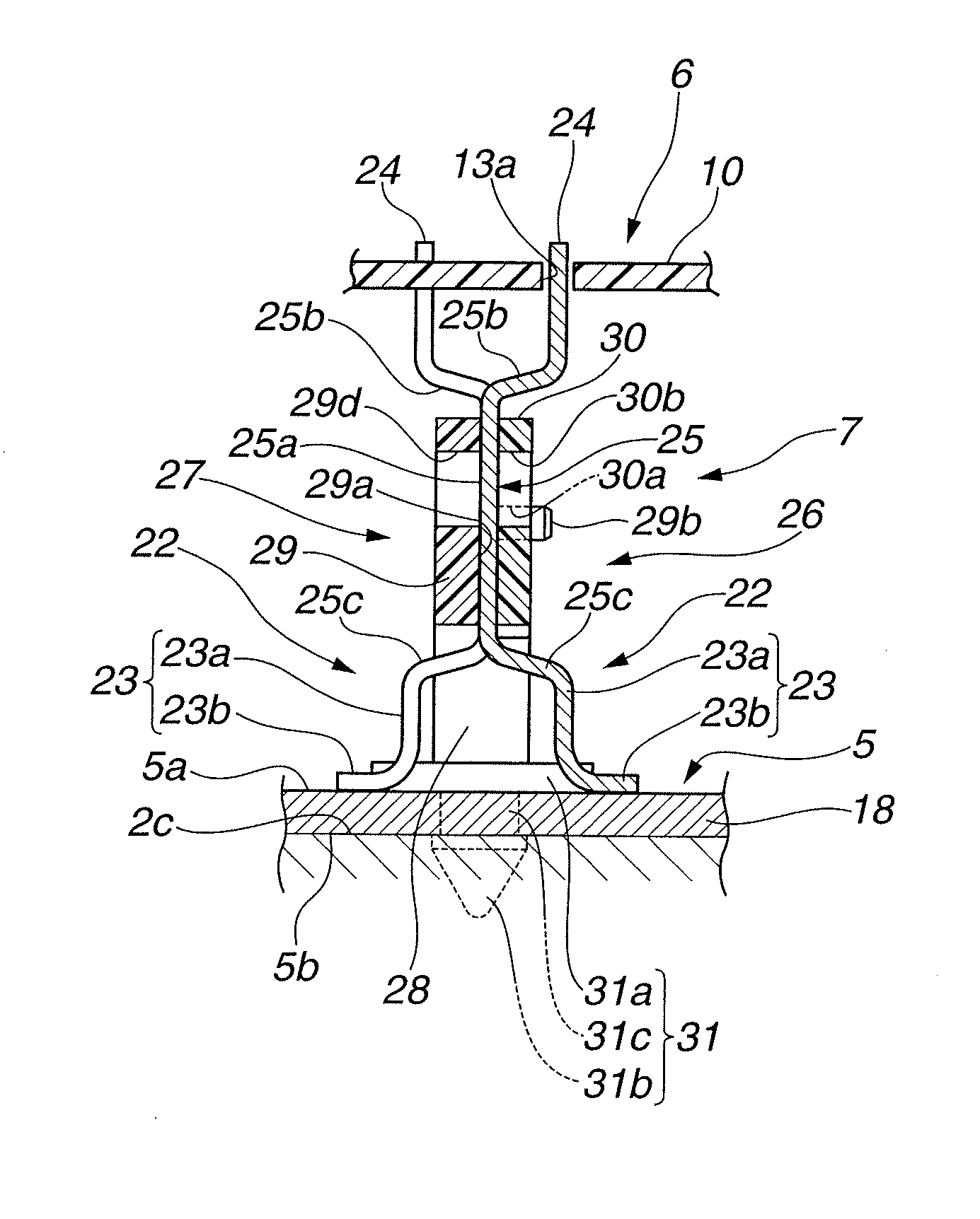
[0046]Therefore, in the first embodiment according to the present invention, as seen from FIGS. 4 and 8, in terminal-pin dense regions A1-A4 of signal-system lead frame 7 in which the intervals between signal-system terminal pins 22 adjacent to each other are minimum, the adjacent signal-system terminal pins 22 are arranged to have such a mounting attitude that the adjacent signal-system terminal pins 22 are angularly displaced from each other by 180 degrees in a direction of rotation about intermediate connecting portion 25a (see FIG. 7). That is, in the respective terminal-pin dense regions A1-A4, signal-system terminal pin 22 having connecting portions 23, 24 located on one side of intermediate connecting portion 25a in the direction perpendicular to the alignment direction of signal-system terminal pins 22, and signal-system terminal pin 22 having connecting portions 23, 24 located on the other side of intermediate connecting portion 25a in the direction perpendicular to the ali...

second embodiment

[0058]FIG. 9 is a perspective view of an electronic control device according to the present invention, showing a power module to which a signal-system lead frame is mounted. In FIG. 9, for the sake of simple illustration, power-system lead frame 8, respective switching elements 9, etc. are omitted.

[0059]As shown in FIG. 9, in electronic control device 200 according to the second embodiment, signal-system terminal pin 22 having connecting portions 23, 24 located on one side of intermediate connecting portion 25a in the direction perpendicular to the alignment direction of signal-system terminal pins 22 (i.e., the alignment direction of intermediate connecting portion 25a), and signal-system terminal pin 22 having connecting portions 23, 24 located on the other side of intermediate connecting portion 25a in the direction perpendicular to the alignment direction of signal-system terminal pins 22 are alternately arranged in the alignment direction of signal-system terminal pins 22 over ...

third embodiment

[0061]As explained above, in view of the fabricating method, it is necessary to ensure certain intervals between respective pads 32 of power module 5 and certain intervals between respective through-holes 13a in the alignment direction of signal-system terminal pins 22. It is generally known that a minimum interval to be provided between the adjacent lands formed around respective pads 32 or through-holes 13a becomes larger in proportion to a thickness of a metal foil forming a conductive pattern thereon. The minimum interval between through-holes 13a of control module 6 which has a conductive pattern formed using a metal foil thinner than that for power module 5 can be reduced as compared to the minimum interval between adjacent pads 32 of power module 5. Therefore, there is provided an electronic control device as shown in FIG. 10 and FIG. 11, in which the control module side connecting portion of the respective signal-system terminal pins and the intermediate connecting portion ...


PUM


Abstract

An electronic control device including a plurality of terminal pins each including a first circuit board side connecting portion connected to a first circuit board, a second circuit board side connecting portion connected to a second circuit board, and an intermediate connecting portion disposed between the first and second circuit board side connecting portions and extending in an overlapping direction in which the first and second circuit boards overlap with each other, the intermediate connecting portions being aligned in a row along a predetermined alignment direction, and the terminal pins at least partially including adjacent two terminal pins formed into a bent shape such that the first circuit board side connecting portion of one of the adjacent two terminal pins is offset relative to the first circuit board side connecting portion of the other adjacent two terminal pins in a direction perpendicular to the predetermined alignment direction.

Description

BACKGROUND OF THE INVENTION[0001]The present invention relates to an electronic control device including a first circuit board and a second circuit board electrically connected with each other through a plurality of terminal pins.[0002]Japanese Patent Application Unexamined Publication No. 2010-111248 discloses a control unit (i.e., an electronic control device) for an electronic power steering which includes a power board as a first circuit board for driving a steering assist electric motor, and a control board as a second circuit board for outputting a drive command to the power board, the power board and the control board being electrically connected with each other through a plurality of connecting terminals formed as terminal pins. Further, the connecting terminals are arranged in a row on the power board in view of an operating efficiency of mounting the connecting terminals onto the power board.SUMMARY OF THE INVENTION[0003]In a case where the connecting terminals are arrange...

Claims


Application Information

Patent Timeline
Patent Type & Authority Patents(United States)
IPC IPC(8): H01R12/00
CPCH01R12/73H01R12/52H01R12/714
Inventor MOTODA, HARUAKI
Owner HITACHI ASTEMO LTD
Why Eureka
Try Eureka