Hermetic compressor

a compressor and hermetic technology, applied in the direction of positive displacement liquid engines, piston pumps, liquid fuel engines, etc., can solve the problems of increased vibrations transmitted from the compression mechanism and the electric motor to the sealed housing, and the sealing housing is upsized, so as to reduce the pressing force, reduce the noise of the hermetic compressor, and restrain the position shift

Inactive Publication Date: 2006-06-08
DAIKIN IND LTD
View PDF5 Cites 6 Cited by
  • Summary
  • Abstract
  • Description
  • Claims
  • Application Information

AI Technical Summary

Benefits of technology

[0035] In the first aspect of the invention, the hermetic compressor is provided with the differential pressure force canceling mechanism (52) to reduce the pressing force acting on the compression mechanism (20) along the axis of the suction passage (40) owing to discharge gas in the sealed housing (10). This restrains the position shift of the compression mechanism (20) and electric motor (30) owing to the difference between the discharge gas pressure and suction gas pressure in the sealed housing (10). Since the position shift of the compression mechanism (20) and electric motor (30) can be thus restrained, the hardness of the resilient member (65) can be set at such a value as required to bear only the gravity acting on the compression mechanism (20) and the electric motor (30). As a result, the compression mechanism (20) and the electric motor (30) are flexibly supported so that vibrations can be inhibited from being transmitted from the compression mechanism (20) and electric motor (30) to the sealed housing (10). Therefore, the noise of the hermetic compressor can be reduced.
[0036] Further, since the position shift of the compression mechanism (20) and electric motor (30) can be restrained in the above manner, this eliminates the need to ensure larger clearance than necessary between the sealed housing (10) and both of the compression mechanism (20) and the electric motor (30). Therefore, the sealed housing (10) can be downsized and in turn the hermetic compressor can be downsized.
[0037] In the second aspect of the invention, the suction passage (40) radially passing through the cylinder (23) is formed in the compression mechanism (20) formed of a rotary fluid machine and the differential pressure force canceling mechanism (52) allows the suction gas pressure to act on the outside surface of the cylinder (23). Therefore, the suction gas pressure acts directly on the cylinder (23) formed with the suction passage (40), which restrains the position shift of the compression mechanism (20) and electric motor (30) with ease and stability.
[0038] In the third aspect of the invention, the differential pressure force canceling mechanism (52) allows the suction gas pressure to act on part of the outside surface of the cylinder (23) opposite to the suction passage (40). Therefore, even if, for example, the differential pressure force canceling mechanism (52) is configured to allow the suction gas pressure to act on a single point on the cylinder (23), it can stably restrain the position shift of the compression mechanism (20) and electric motor (30). This simplifies the structure of the differential pressure force canceling mechanism (52) and thereby reduces the cost of the hermetic compressor.
[0039] In the fourth aspect of the invention, the differential pressure force canceling mechanism (52) is formed with the suction pressure chamber (50) and the communicating passage (51) and is configured to allow the suction gas pressure led into the suction pressure chamber (50) to act on the cylinder (23). Therefore, the differential pressure force canceling mechanism (52) can be achieved with a relatively simple structure, which restrains the hermetic compressor from increasing in cost for the reason of provision of the differential pressure force canceling mechanism (52).
[0040] In the fifth aspect of the invention, since the communicating passage (51) of the differential pressure force canceling mechanism (52) is formed in the cylinder (23), this eliminate the need to provide a separate member constituting the communicating passage (51). This restrains the number of parts from increasing for the reason of provision of the differential pressure force canceling mechanism (52) and avoids the upsizing of the hermetic compressor.

Problems solved by technology

Therefore, the coil spring should be hardened accordingly, which causes a problem that vibrations transmitted from the compression mechanism and the electric motor to the sealed housing are increased.
As a result, a problem arises that the sealed housing is upsized.

Method used


Image

  • Hermetic compressor
  • Hermetic compressor
  • Hermetic compressor

Examples


Embodiment Construction

[0052] Embodiments of the present invention will be described below in detail with reference to the drawings.

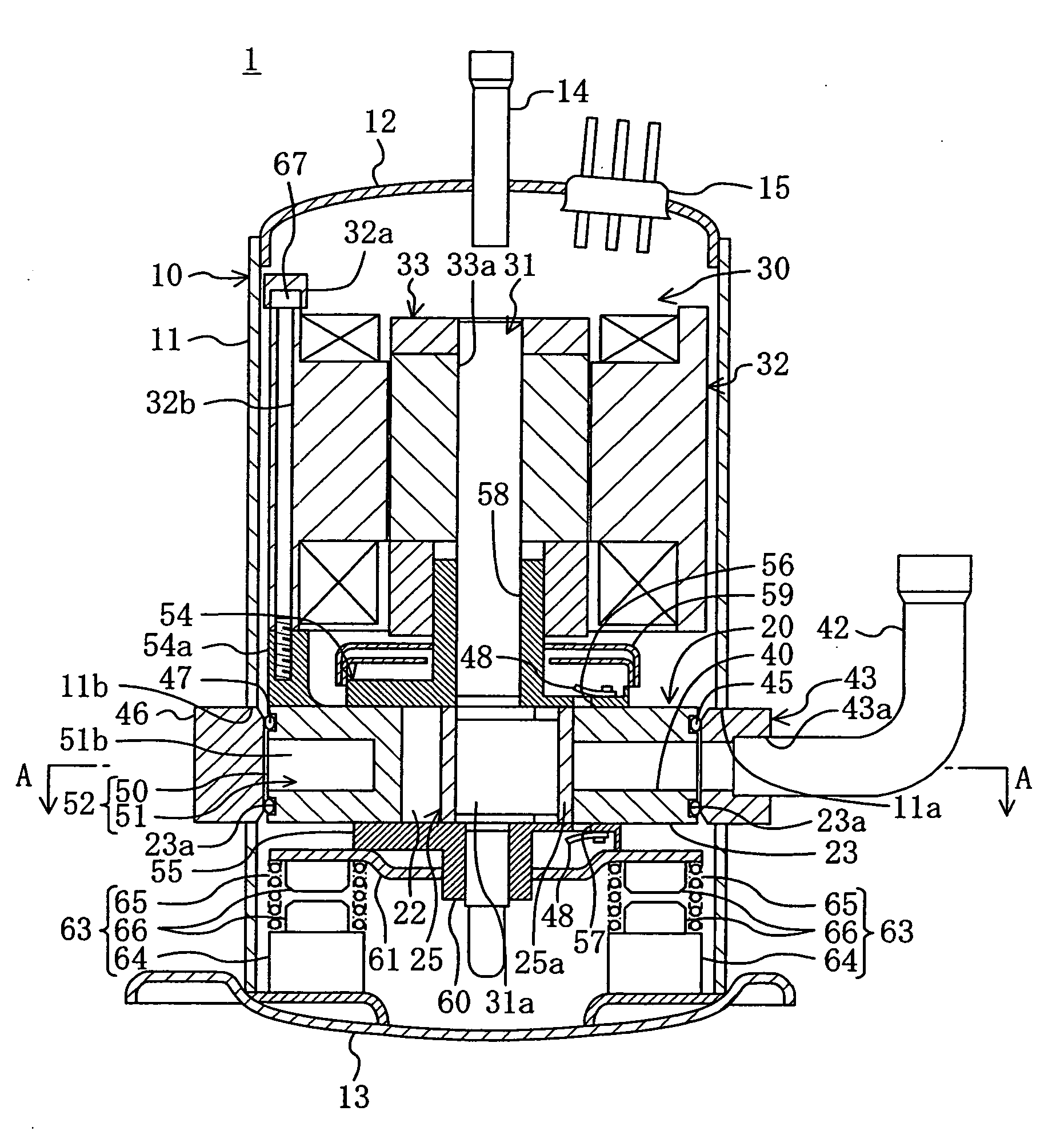
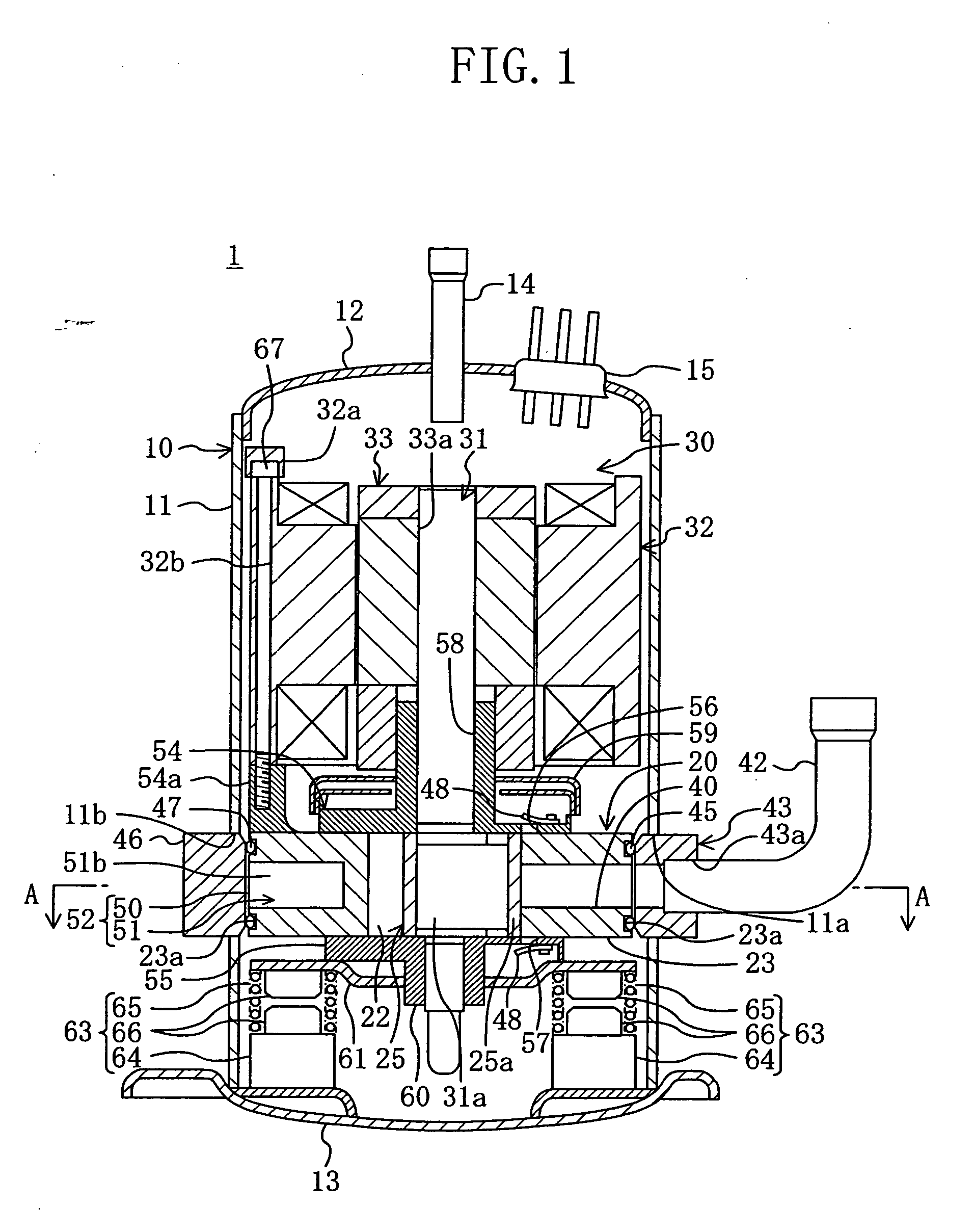
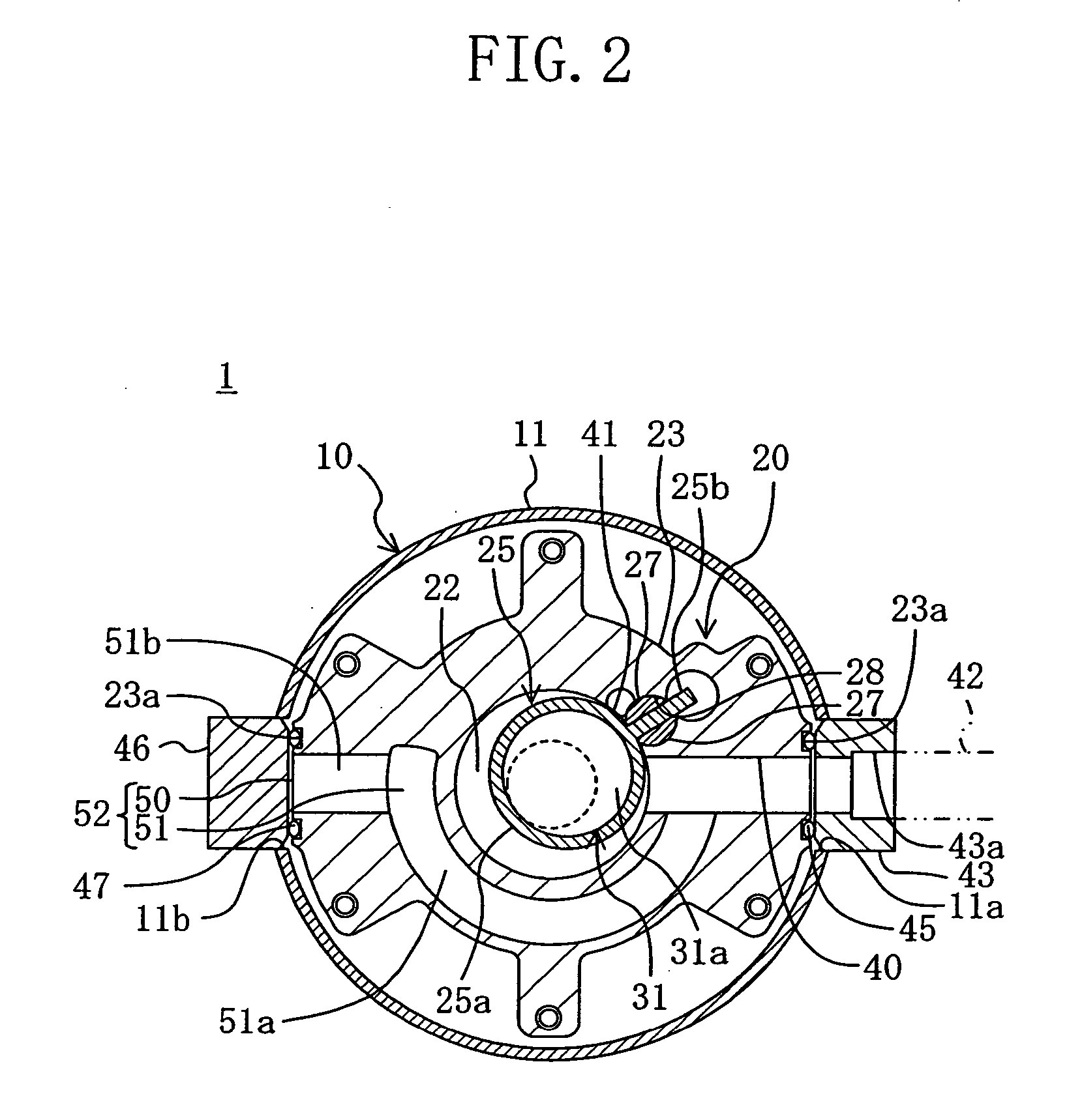
[0053]FIG. 1 shows an embodiment of the present invention applied to a so-called “rocking piston type” rotary compressor (1). This compressor is configured to compress refrigerant during a cooling cycle in an air conditioner. In this compressor (1), a sealed housing (10) contains a compression mechanism (20) and an electric motor (30) which are connected to each other through a drive shaft (31). The electric motor (30) is placed above and joined integrally to the compression mechanism (20). The compression mechanism (20) is resiliently supported to the sealed housing (10) via mounting mechanisms (63).

[0054] The sealed housing (10) is formed in a size that a predetermined clearance is left between the sealed housing (10) and both of the compression mechanism (20) and the electric motor (30) so that the compression mechanism (20) and electric motor (30) in operation cannot be...


PUM


Abstract

A compression mechanism has a cylinder, a suction passage and a discharge passage. The suction passage of a cylinder is connected to a suction pipe. The discharge passage is open to an inner space of a sealed housing. A discharge gas is discharged through a discharge pipe. The cylinder is formed with a communicating passage extending from a suction passage to a suction pressure chamber to lead a suction gas in the suction passage into the suction pressure chamber and thereby allow a pressure of the suction gas in the suction passage to act on an outside surface of the cylinder.

Description

TECHNICAL FIELD [0001] This invention relates to a hermetic compressor in which a compression mechanism and an electric motor are contained in a sealed housing, and particularly relates to its structure in which the compression mechanism and the electric motor are resiliently supported in the sealed housing. BACKGROUND ART [0002] An example of known hermetic compressors of this type is one in which an electric motor is integrally provided on top of a compression mechanism and a coil spring is interposed between the compression mechanism and the inner surface of the bottom wall of a sealed housing to inhibit the transmission of vibrations of the compression mechanism and the electric motor to the sealed housing and thereby reduce the noise of the compressor in operation (see, for example, Patent Document 1: Japanese Unexamined Patent Publication No. H01-203688 (Pages 3 and 4 and FIG. 1)). [0003] In the above hermetic compressor in Patent Document 1, the upstream end of a suction pass...

Claims


Application Information

Patent Timeline
Patent Type & Authority Applications(United States)
IPC IPC(8): F04B35/04F04B17/00F04C29/12F01C21/10F04C18/32F04C23/00F04C27/00F04C29/00F04C29/06
CPCF01C21/10F01C21/104F04B39/0044F04B39/123F04C18/322F04C23/008F04C27/00F04C27/008F04C29/0021F04C29/122F04C2230/60F04C2240/30F04C2240/806F04C2270/12
Inventor SHIMIZU, TAKASHISHIBAMOTO, YOSHITAKAASANO, YOSHINARI
Owner DAIKIN IND LTD
Why Eureka
Try Eureka