Optical device and projector having the optical device

a technology of optical devices and projectors, which is applied in the direction of optical elements, instruments, television systems, etc., can solve the problems of reducing the size of the optical device, deteriorating the polarization film, and easily deteriorating the film

Inactive Publication Date: 2004-02-19
SEIKO EPSON CORP
View PDF4 Cites 15 Cited by
  • Summary
  • Abstract
  • Description
  • Claims
  • Application Information

AI Technical Summary

Problems solved by technology

Such polarization plate ordinarily has a resin polarization film adhered on a glass base plate and such polarization film is likely to be deteriorated (e.g. distorted) on account of rise in temperature caused by absorbing the light.
Especially, the irradiation-side polarization plate has to absorb all the unnecessary tight irradiated by the liquid crystal panel in projecting a full-black image onto the screen, thus being easily to be deteriorated.
However, since the size of the optical device is reduced in accordance with increase in illuminance and size reduction of recent projector and the optical components such as a liquid crystal panel and polarization plate are closely installed, sufficient cooling air cannot be flow through the gap between the respective optical components, so that the polarization film, especially the radiation-side polarization film cannot be sufficiently cooled.
Though it is possible to increase the flow rate of the cooling air for efficiently cooling the polarization film, the size of the cooling fan or the number of revolution has to be increased, which runs counter to the requirement of size and weight reduction of projector and inevitably increases the noise,
On the other hand, since a cross dichroic prism ordinarily is difficult to be thermally expanded as compared to a metal base, the cross dichroic prism does not follow the heat expansion of the base.
Accordingly, the relative positions between the liquid crystal panel and the cross dichroic prism and, as a result, between the three liquid crystal panels may be shifted, thus causing shift between the picture elements to be combined to deteriorate the image quality of the combined image.
The same disadvantage may be not applied only to a polarization film but also found when an optical conversion film such as viewing angle compensating film and phase film having other optical function and easily causing thermal deterioration is used.
According to the above arrangement, since the optical conversion film is adhered on sapphire glass, crystal and silica glass having high thermal conductivity, the heat generated on the optical conversion film can be transferred to the cooling device or the base, thus further lengthening the life of the optical conversion film.
According to the above arrangement, since the base and the cooling device are made of metal having high thermal conductivity, the heat generated on the optical conversion film can be transferred to the cooling device and the base, thus further lengthening the life of the optical conversion film.

Method used


Image

  • Optical device and projector having the optical device
  • Optical device and projector having the optical device
  • Optical device and projector having the optical device

Examples


first embodiment

[0073] [First Embodiment]

[0074] A projector according to a first embodiment of the present invention will be described below with reference to attached drawings.

[0075] [1-1. Primary Arrangement of Projector]

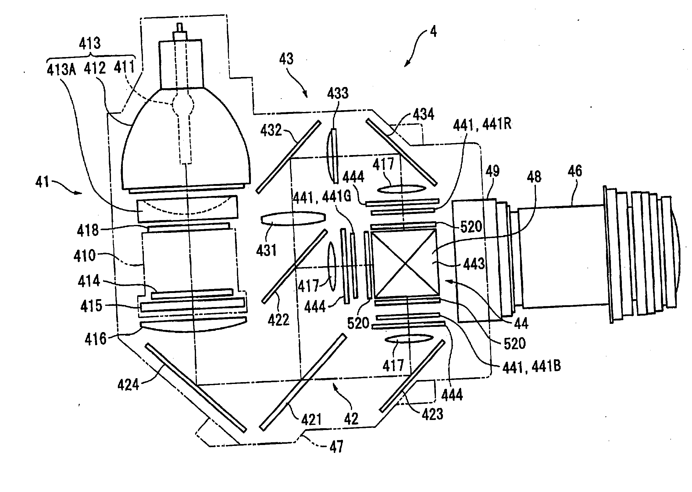
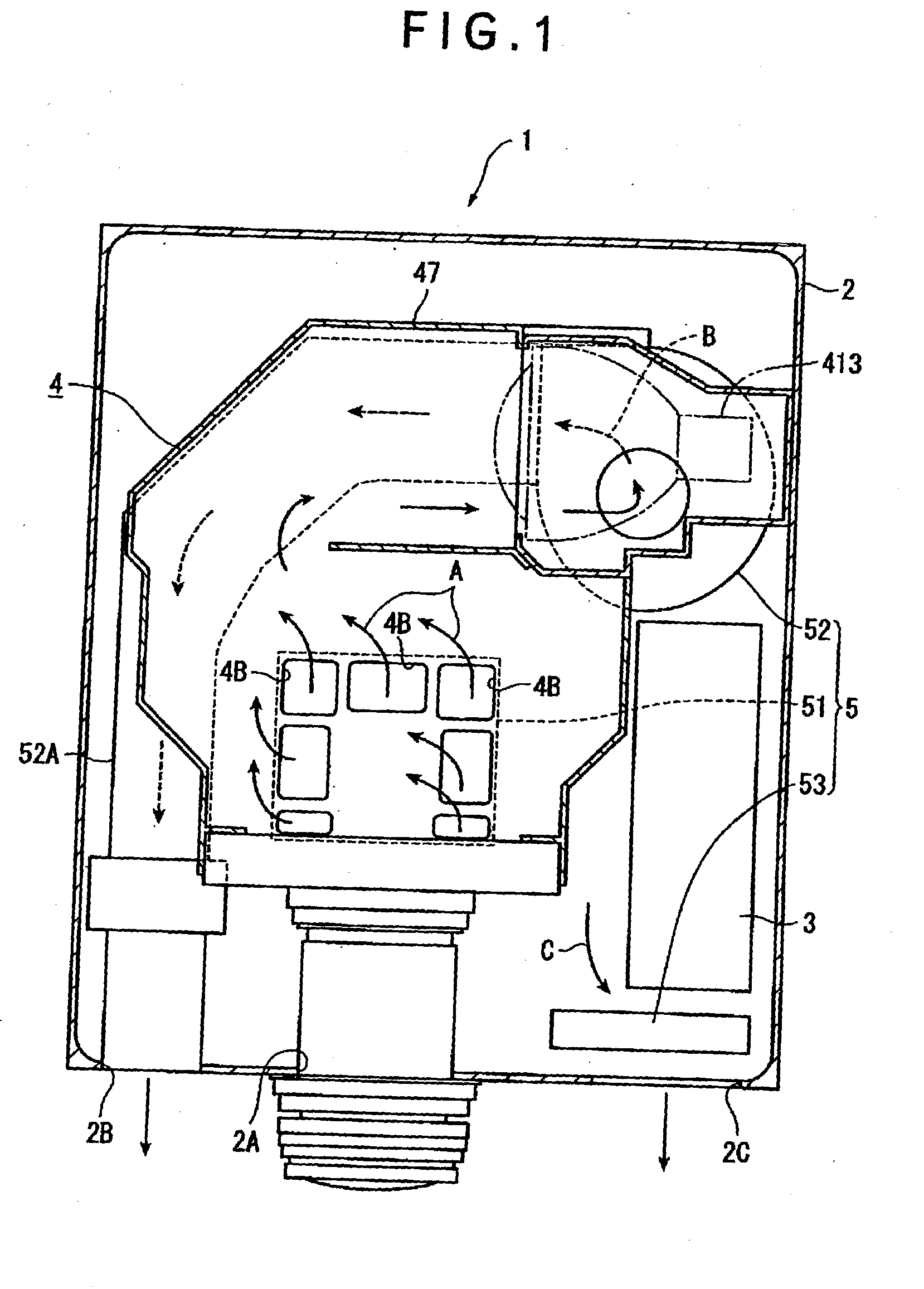
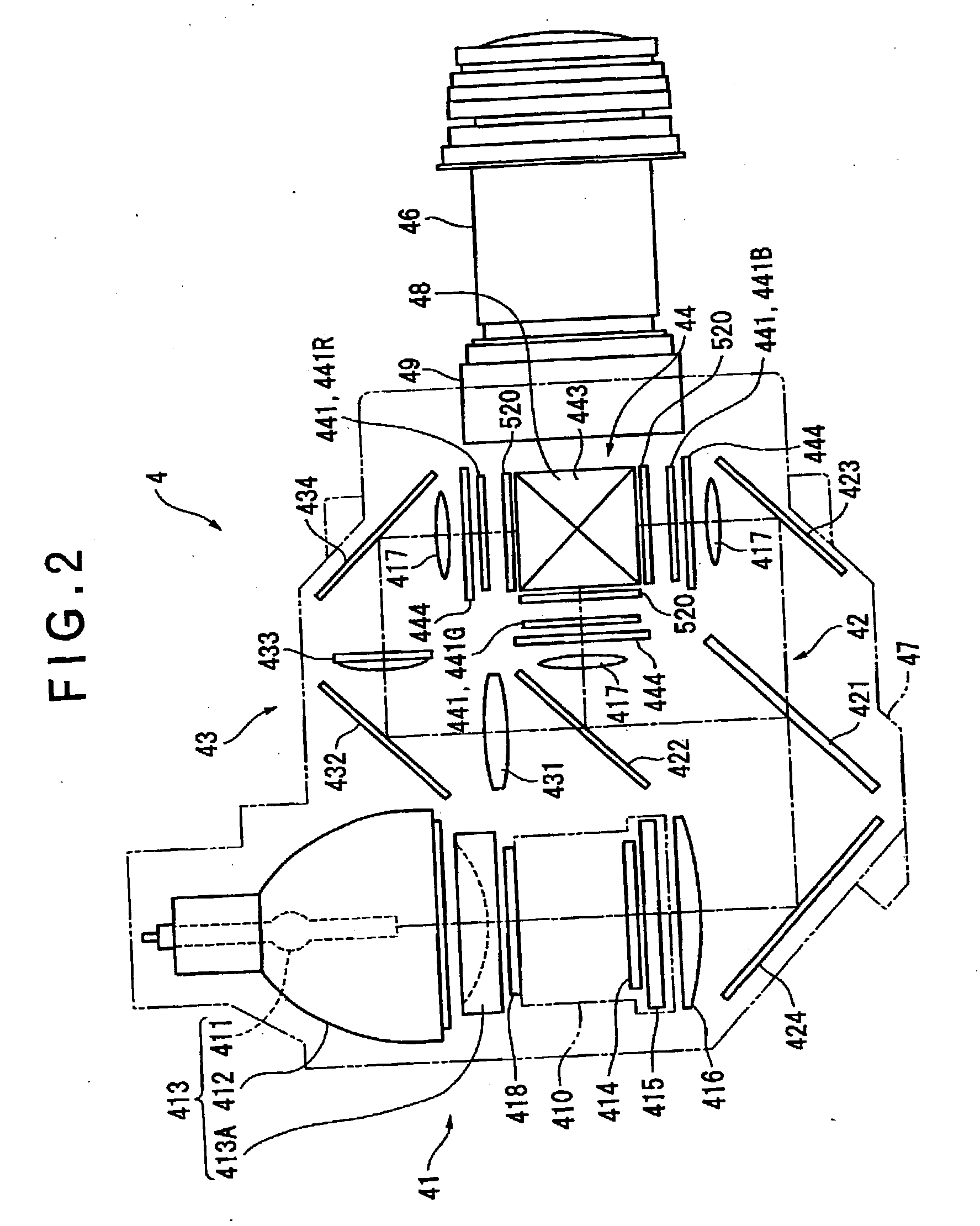
[0076] FIG. 1 is a plan view schematically showing an internal construction of a projector 1 according to the first embodiment of the present invention The projector 1 has an approximately rectangular-parallelepiped resin-made exterior case 2, an optical unit 4 for forming an optical image in accordance with image information by optically processing a light beam irradiated by a light source 413, a cooling unit 5 for releasing heat generated inside the projector 1, and a power source unit 3 for feeding electric power supplied from the outside to the units 4, 5 and the like.

[0077] The exterior case 2 accommodates the units 3 to 5, which includes (not specifically shown) an upper case constituting the upper side, front side and lateral side of the projector 1 and a lower case consti...

second embodiment

[0162] [Second Embodiment]

[0163] Next, a projector according to a second embodiment of the present invention will be described below with reference to attached drawings.

[0164] The projector according to the second embodiment differs from the projector 1 of the first embodiment only in the arrangement of the liquid crystal panel as a part of the optical device body 48. Accordingly, the same reference numeral will be attached to the same or corresponding component as the first embodiment to omit or simplify the description thereof.

[0165] [2-1 Arrangement of Optical Device Body]

[0166] FIG. 5 is an exploded perspective view showing an optical device body 48A of the optical device 44. FIG. 6 is a perspective view showing the optical device body 48A. Incidentally, as in the first embodiment, only the liquid crystal panel 441G side will be illustrated as an example and the illustration of the other liquid crystal panels 441R and 441B will be omitted.

[0167] As shown in FIG. 5, the optical d...

third embodiment

[0180] [Third Embodiment]

[0181] Next, a projector according to third embodiment of the present invention will be described below.

[0182] The projector according to the third embodiment of the present invention differs from the projector 1 of the first embodiment only in the arrangement of a part of the optical device body. Accordingly, the same reference numeral will be attached to the component identical or corresponding to the components of the first embodiment to omit or simplify the description thereof.

[0183] Further, the arrangement of the liquid crystal panel 441 of the second embodiment, i.e. the holding plate 810, the liquid crystal panel 441 and the heat sink 820 may be used in the present embodiment.

[0184] [3-1. Arrangement of Optical Device Body]

[0185] FIG. 8 is an exploded perspective view showing the optical device body 48B of the optical device 44. FIG. 9 is a vertical cross sectional view showing the optical device body 48B. Incidentally, as in the first embodiment, on...


PUM


Abstract

An optical device has: a metal cooling device (500) disposed between a liquid crystal panel (441) and a light-incident side of a cross dichroic prism (443) and having a holding surface for holding polarization plates (521, 522) attached with a polarization films (521A and 522A) in a mutually spaced manner, the cooling device cooling the polarization films; a base (445) provided on the upper and lower sides of the cross dichroic prism (443) and having a cooling device attachment surface (449A) for the cooling device (500) to be attached; and a fixing member (600) provided on a light-incident side of the cross dichroic prism for locating and fixing the liquid crystal panel (441) on the light-incident side, the fixing member (600) being formed with a attachment surface (631) on which a pin (730) for mounting the liquid crystal panel (441) is formed.

Description

[0001] 1. Field of the Invention[0002] The present invention relates to an optical device and a projector having the optical device.[0003] 2. Description of Related Art[0004] Conventionally, a three-plate projector including a color-separating optical system for separating a light beam irradiated by a light source lamp into three color lights of R, G and B with a dichroic mirror, a three optical modulators (liquid crystal panel) for modulating the separated light beam per each color light in accordance with image information, and an optical device having a cross dichroic prism for combining the light beam modulated by the respective liquid crystal panels has been used.[0005] In an optical device of such a projector, in order to accurately combine the light beam irradiated by the three liquid crystal panels, the three liquid crystal panels are mounted on the cross dichroic prism with high accuracy so that the corresponding picture elements of the three liquid crystal panels are accur...

Claims


Application Information

Patent Timeline
Patent Type & Authority Applications(United States)
IPC IPC(8): G03B35/00H04N5/74
CPCG03B35/00H04N9/3141H04N5/7441
Inventor FUJIMORI, MOTOYUKIMIYAZAWA, ATSUSHI
Owner SEIKO EPSON CORP
Why Eureka
Try Eureka