Dental prosthesis

a technology for teeth and hinges, applied in dentistry, dental surgery, medical science, etc., can solve the problems that the requirements placed on the screw connection of the spectacle hinge cannot be compared to the requirements placed, and achieve the effect of tight screw connection, increased friction resistance, and avoiding the possibility of self-loosening the screw connection

Inactive Publication Date: 2015-02-10
REDTENBACHER PRAZISIONSTEILE +1
View PDF16 Cites 7 Cited by
  • Summary
  • Abstract
  • Description
  • Claims
  • Application Information

AI Technical Summary

Benefits of technology

[0007]By providing at least two conical sections which are consecutive in the axial direction and which have different diameters with respect to the conical shoulder, it occurs as a result of the different opening angles of the cones of the shoulder on the one hand and the conical sections of the screw cap on the other hand when the cap screw is tightened that at first the one conical section of the cap screw is pressed against the conical shoulder of the abutment under elastic and plastic deformation of the conical shoulder of the abutment and the respective conical section of the cap screw before the other conical section comes to rest thereon and subsequently forms an additional sealing surface at least under elastic deformation of the cooperating conical surfaces. The required tightness of the screw connection can thus be ensured by the resulting, at least two-stage sealing of the screw cap in relation to the abutment. Furthermore, the frictional resistance is increased by the plastic and elastic deformation of the cooperating conical surfaces in such a way that the likelihood of self-loosening of the screw connection can be excluded.
[0008]Especially simple constructional conditions are obtained when the two conical sections of the cap screw have the same cone angle, which is not mandatory however. If the cone angles of the cap screw are larger than the cone angle of the conical shoulder, the sealing surfaces are advantageously obtained in the region of the largest diameter of the two cone sections of the conical cap part.
[0009]For the production of the two cone sections it is recommended to provide these cone sections at an axial distance from each other. Furthermore, advantageous conditions are further obtained concerning the sealing areas when the cap screw is tightened in that the conical section engaging with play in the shoulder cone during contact of the one conical section on the conical shoulder has a shorter axial length because when the cap screw is tightened the engagement length of said conical section of the cap screw engaging initially with play in the shoulder cone is respectively shorter.

Problems solved by technology

The requirements placed on screw connections of spectacle hinges cannot be compared to the requirements placed on the screw connections between the abutment and implant body however since the problem of tightness is irrelevant in screw connections for spectacle hinges.

Method used


Image

  • Dental prosthesis
  • Dental prosthesis
  • Dental prosthesis

Examples


Embodiment Construction

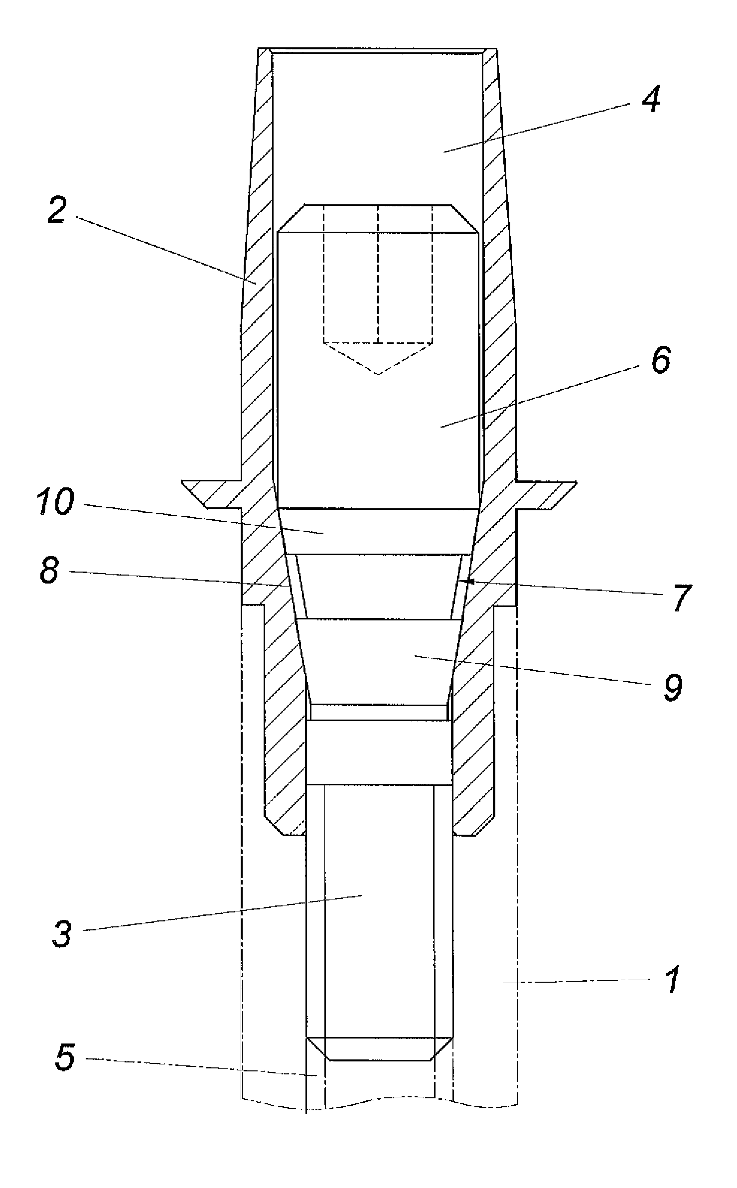
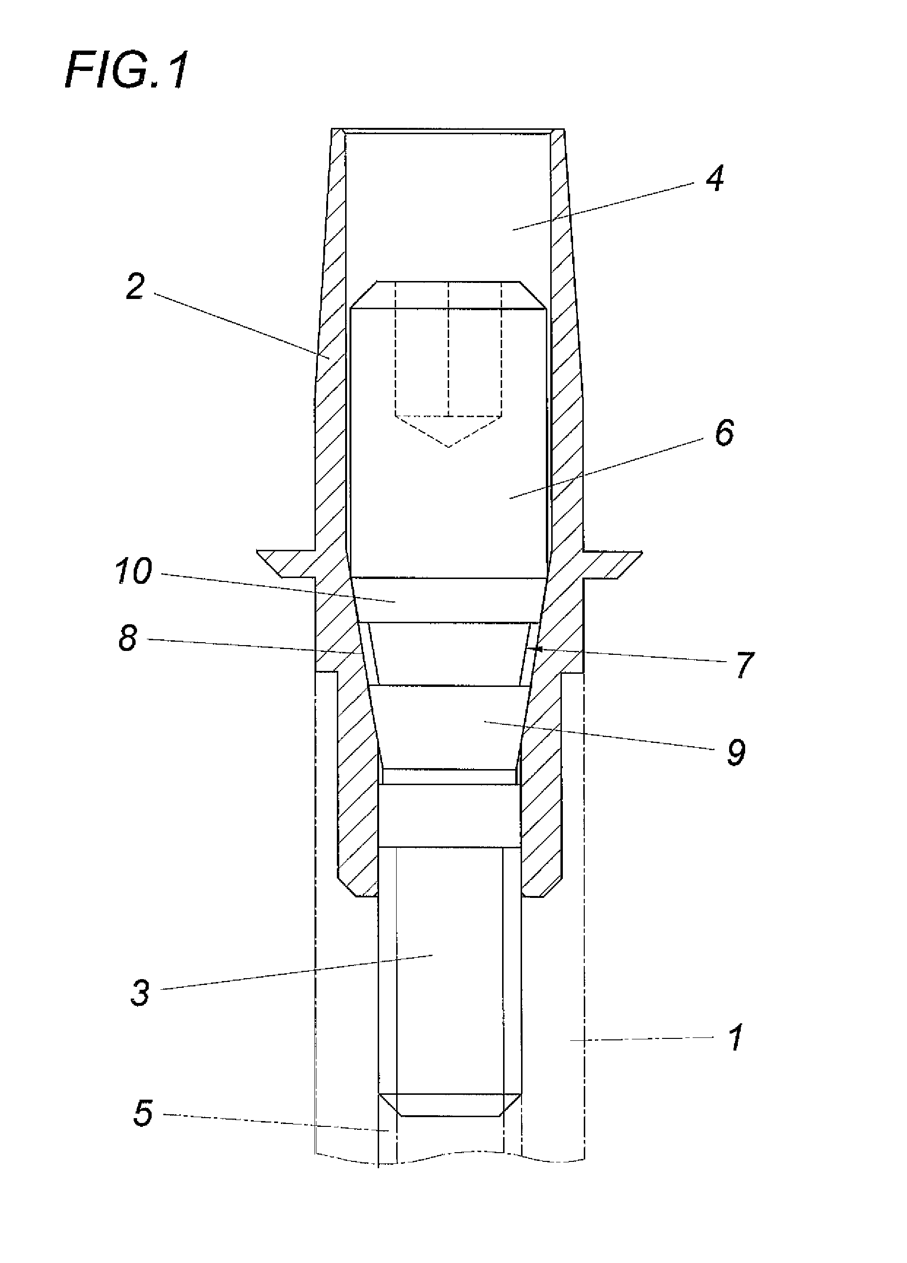
[0013]The dental prosthesis according to FIG. 1 comprises in the conventional manner an implant body 1 to be inserted into the jawbone and indicated by the dot-dash line for accommodating an abutment 2 for a dental prosthesis. Said abutment 2 is connected by means of a cap screw 3 to the implant body 1. For this purpose, the abutment 2 is provided with a passage opening 4, into which the cap screw 3 is inserted which engages in an internal thread 5. The screw cap 6 comprises a conical cap part 7 which cooperates with a conical shoulder 8 of the abutment 4 and presses the abutment 2 into its receptacle in the implant body 1 via said conical shoulder 8.

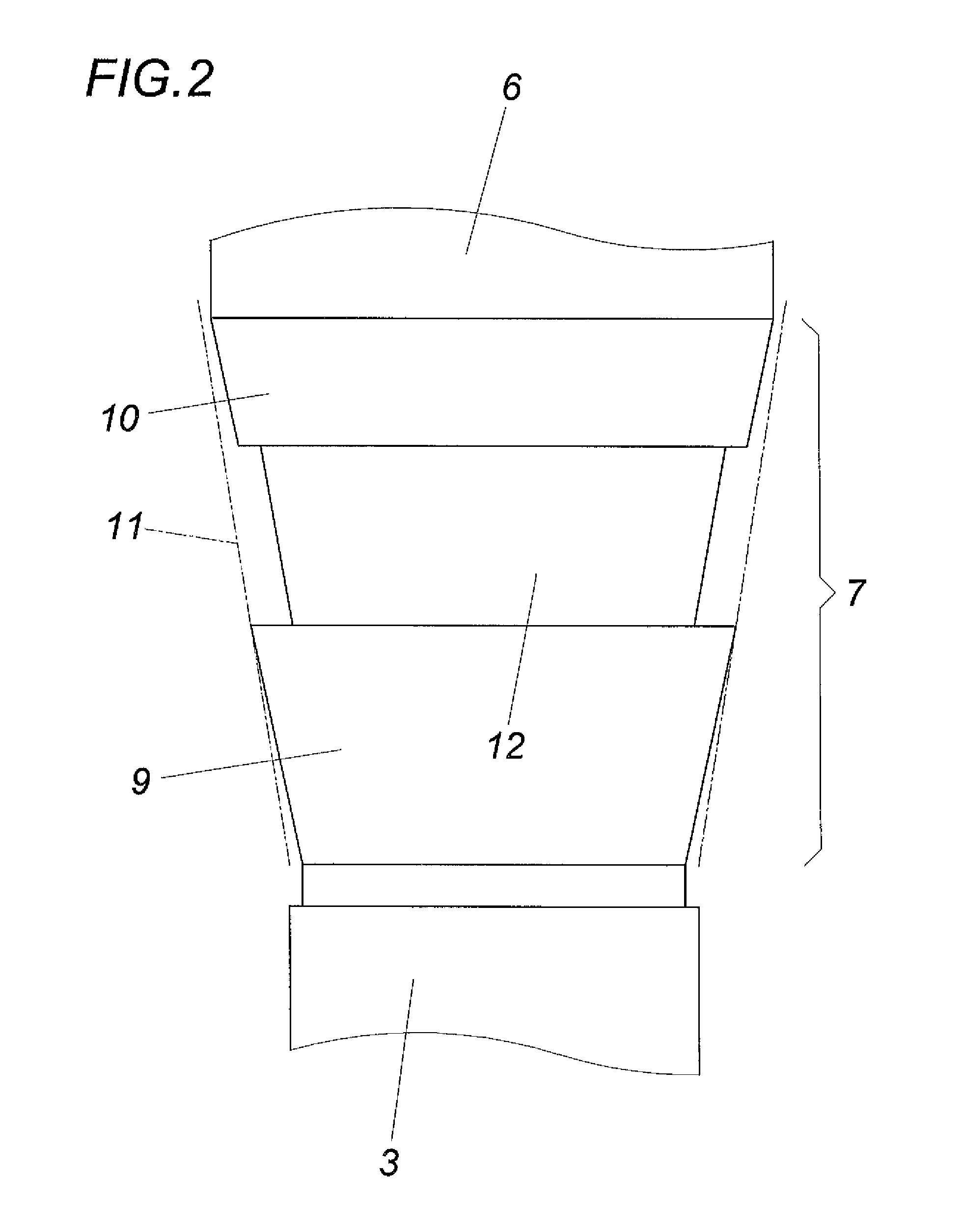
[0014]As is shown especially in FIG. 2, the conical cap part 7 comprises two consecutive conical sections 9 and 10 in the axial direction. Although said conical sections 9 and 10 have a corresponding cone angle, the cone tips are disposed at an axial distance from each other on the screw axis, so that the one conical section 9 already s...


PUM


Abstract

The invention relates to a dental prosthesis, comprising an implant body (1) and an abutment (2) that can be inserted into a receptacle of the implant body (1), said abutment (2) forming a passage opening (4) for accommodating a cap screw (3) that engages in an internal thread (5) of the implant body (1), which screw is supported by means of a conical cap part (7) of the cap screw (3) on a conical shoulder (8) of the abutment (2). In order to provide advantageous constructional conditions it is proposed that the conical cap part (7) has at least two consecutive conical sections (9, 10) in the axial direction, which conical sections have an opening angle that differs from the opening angle of the conical shoulder (8), and when the one conical section (9) contacts the conical shoulder (8) without pressure the other conical section (10) engages in the shoulder cone (11) with play.

Description

CROSS REFERENCE TO RELATED APPLICATIONS[0001]This application is the National Stage of PCT / AT2012 / 050045 filed on Apr. 5, 2012, which claims priority under 35 U.S.C. §119 of Austrian Application No. A 560 / 2011 filed on Apr. 20, 2011, the disclosure of which is incorporated by reference. The international application under PCT article 21(2) was not published in English.1. FIELD OF THE INVENTION[0002]The invention relates to a dental prosthesis, comprising an implant body and an abutment that can be inserted into a receptacle of the implant body, said abutment forming a passage opening for accommodating a cap screw that engages in an internal thread of the implant body, which screw is supported by means of a conical cap part on a conical shoulder of the abutment.2. DESCRIPTION OF THE PRIOR ART[0003]Dental prostheses are usually arranged in such a way that an implant body inserted into the jawbone accommodates an abutment for building the dental prosthesis. This abutment is connected b...

Claims


Application Information

Patent Timeline
Patent Type & Authority Patents(United States)
IPC IPC(8): A61C8/00
CPCA61C8/0069A61C8/0068A61C8/0072A61C8/0037
Inventor BUCHEGGER, HARALD
Owner REDTENBACHER PRAZISIONSTEILE
Why Eureka
Try Eureka